Switch
a technology of switch and switch body, applied in the field of switch, can solve the problems of increasing assembly man-hour, inability to realize compact switch, increasing cost, etc., and achieve the effect of stable operation characteristi
- Summary
- Abstract
- Description
- Claims
- Application Information
AI Technical Summary
Benefits of technology
Problems solved by technology
Method used
Image
Examples
first embodiment
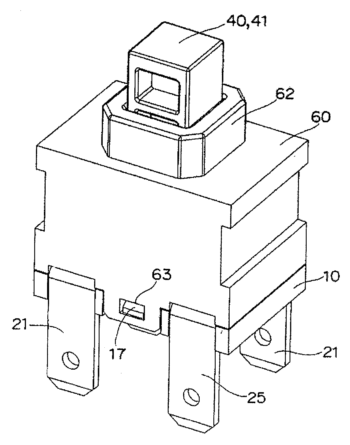
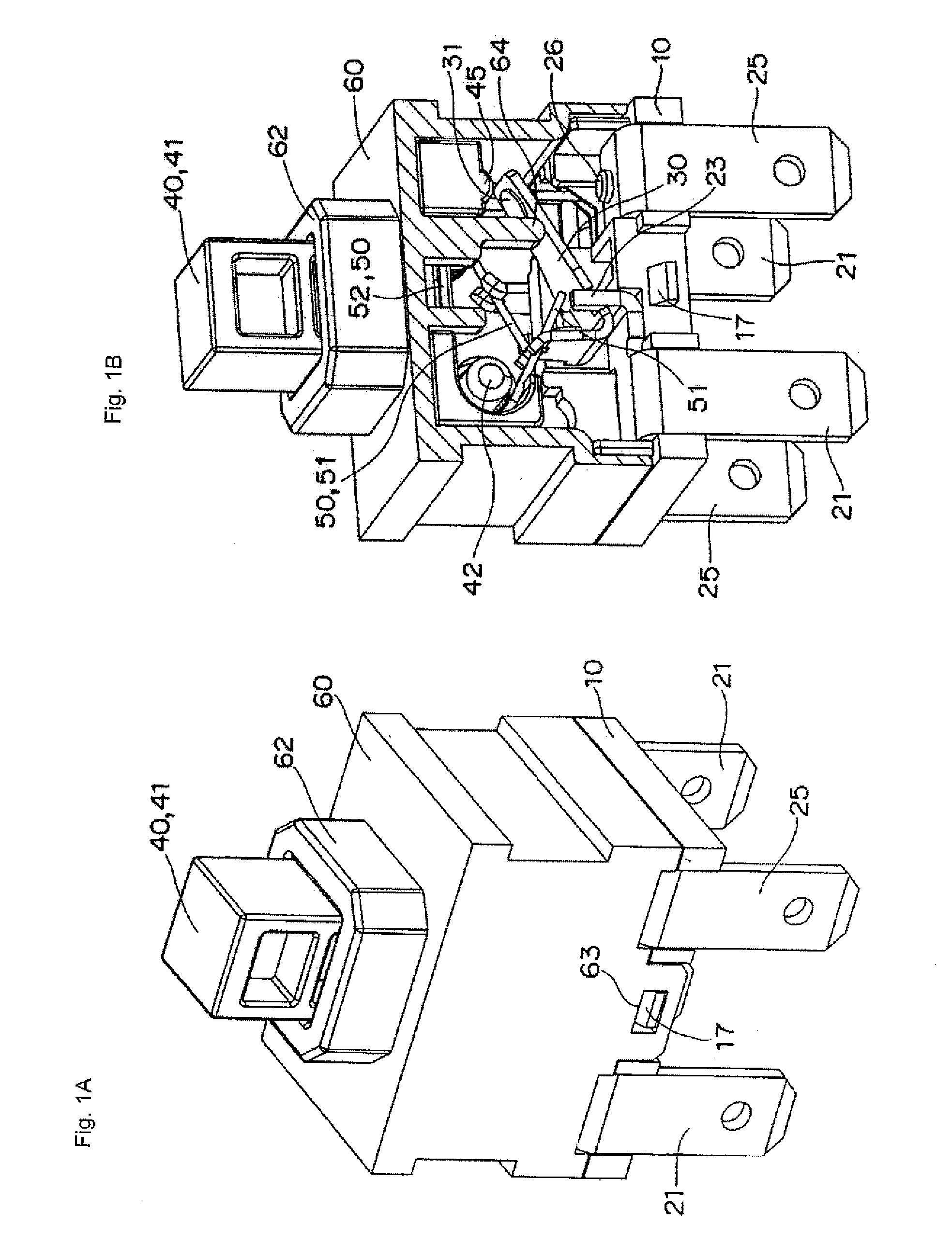
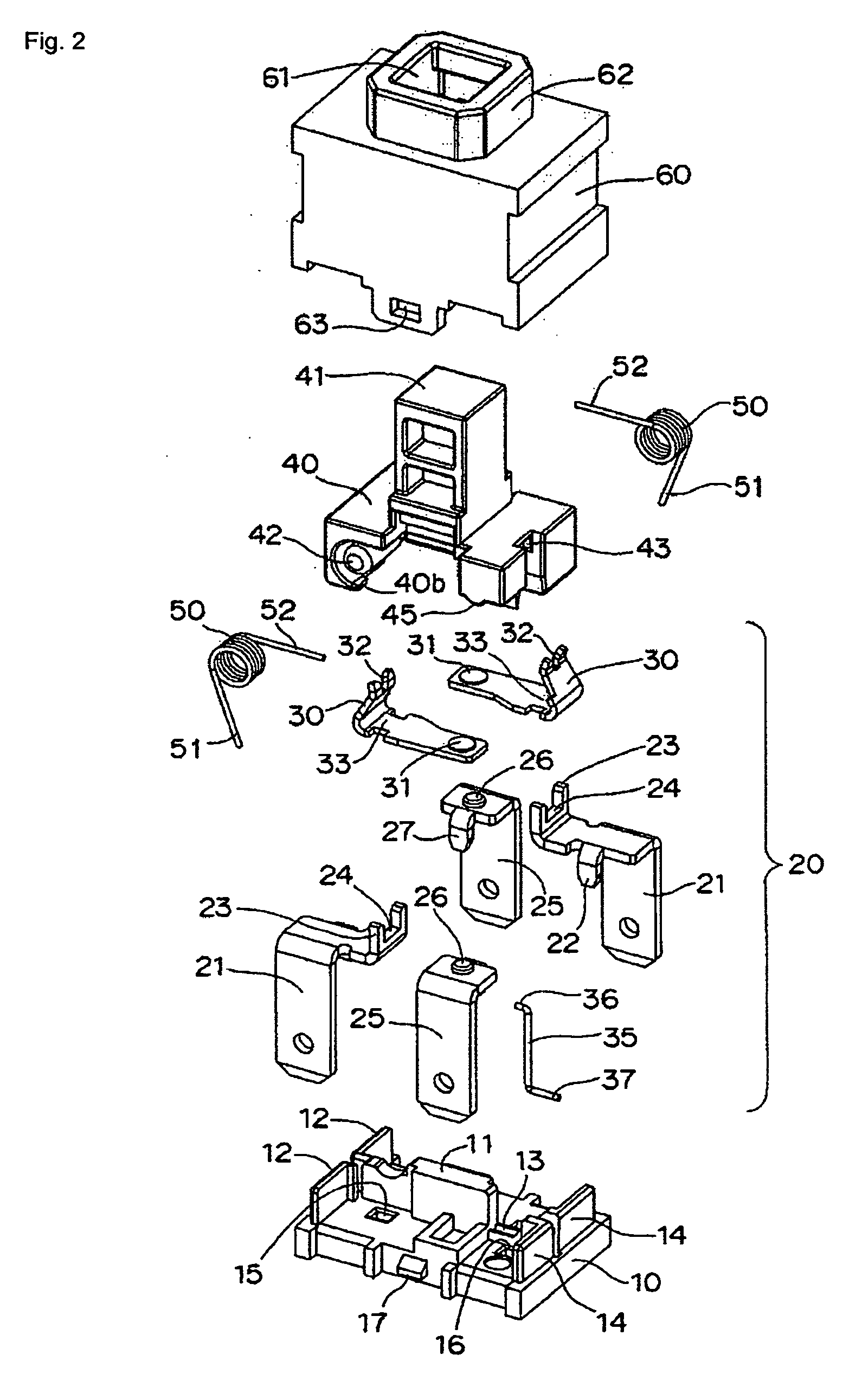
[0046]Preferred embodiments of the invention will be described below with reference to the accompanying drawings. Referring to FIGS. 1 to 8, a switch according to the invention includes a base 10, two sets of contact mechanisms 20 and 20, a plunger 40, and a housing 60. The two sets of contact mechanisms 20 and 20 are assembled into the base 10. The plunger 40 includes a pair of coil springs 50 and 50 and a lock pin 35, and the plunger 40 works the contact mechanism 20. The housing 60 is fitted in the base 10 to cover the contact mechanism 20 therewith, and the housing 60 supports the plunger 40 while the plunger 40 can vertically be moved.
[0047]Referring to FIG. 2, in the base 10, a pair of insulating walls 12 and 12 is projected on the same straight line from one end portion side of a partition 11 projected in the center of an upper surface of the base 10, an engagement groove 13 is provided on an extended line on the other end portion side, and a pair of insulating walls 14 and 1...
fourth embodiment
[0066]That is, as shown in FIGS. 13 to 16, the switch of the fourth embodiment includes the base 10, the two sets of contact mechanisms 20 and 20, the plunger 40, and the housing 60. The two sets of contact mechanisms 20 and 20 are assembled into the base 10. The plunger 40 includes the pair of coil springs 50 and 50 and the lock pin 35, and the plunger 40 works the contact mechanism 20. The housing 60 is fitted in the base 10 to cover the contact mechanism 20 therewith, and the housing 60 supports the plunger 40 while the plunger 40 can vertically be moved.
[0067]Referring to FIG. 14, in the base 10, the pair of insulating walls 12 and 12 is projected on the same straight line from one end portion side of the partition 11 projected in the center of the upper surface of the base 10, the engagement groove 13 is provided on the extended line on the other end portion side, and the pair of insulating walls 14 and 14 is projected on the same straight line from the other end portion side o...
PUM
 Abstract
Description
Claims
Application Information
 - R&D
- Intellectual Property
- Life Sciences
- Materials
- Tech Scout
- Unparalleled Data Quality
- Higher Quality Content
- 60% Fewer Hallucinations
Browse by: Latest US Patents, China's latest patents, Technical Efficacy Thesaurus, Application Domain, Technology Topic, Popular Technical Reports.
© 2025 PatSnap. All rights reserved.Legal|Privacy policy|Modern Slavery Act Transparency Statement|Sitemap|About US| Contact US: help@patsnap.com


