
Rotary-wing miniature gyro helicopter

a rotary-wing, miniature technology, applied in the field of miniature rotary-wing rotary-wing gyro helicopters, can solve the problems of difficult to get the rotor spinning fast enough for flight, and the problems of toys, and achieve the effect of enhancing the gyroscopic stability of the gyro helicopter

Inactive Publication Date: 2009-01-08
SPIN MASTER LTD
View PDF6 Cites 19 Cited by
  • Summary
  • Abstract
  • Description
  • Claims
  • Application Information

AI Technical Summary

Benefits of technology

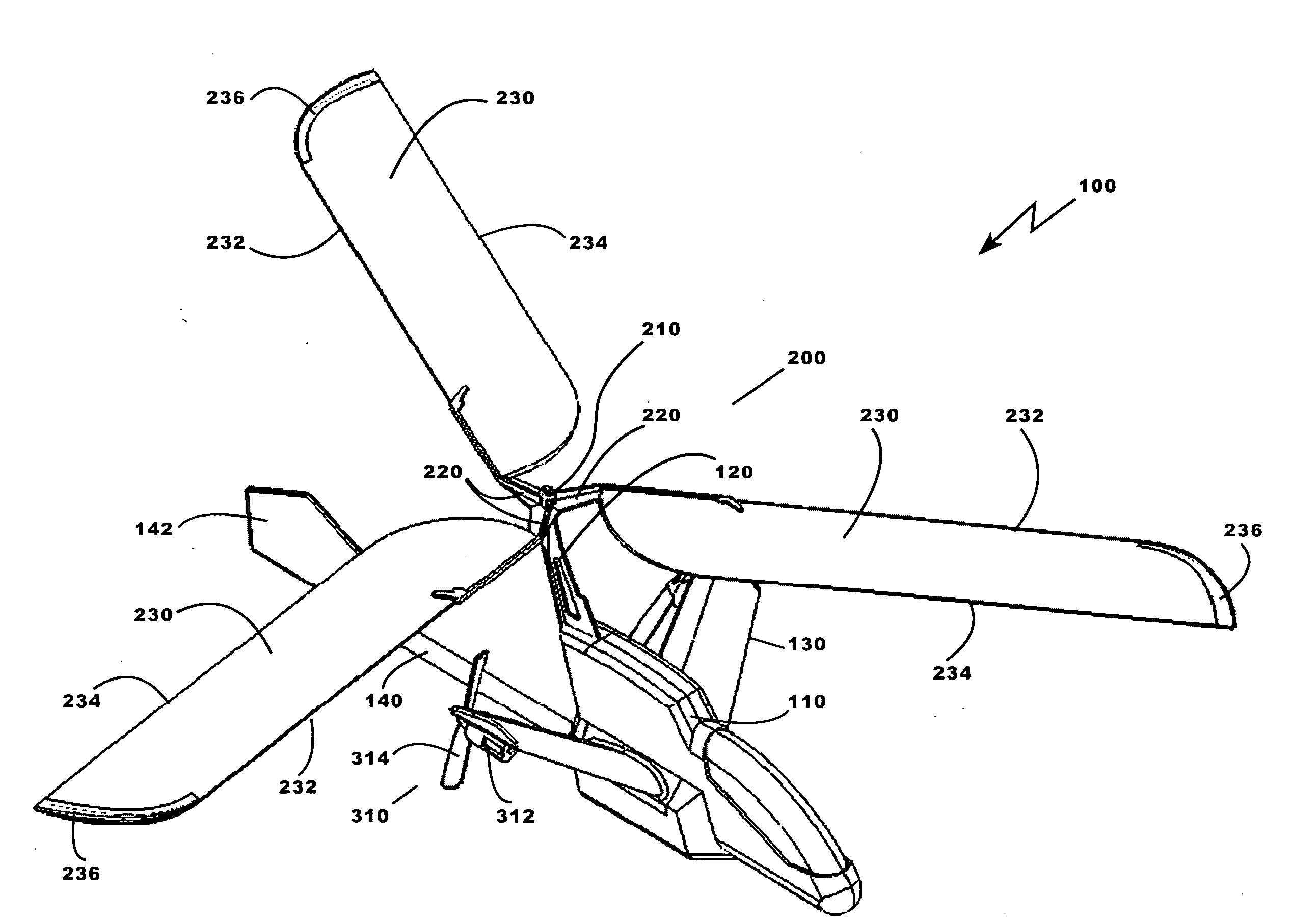
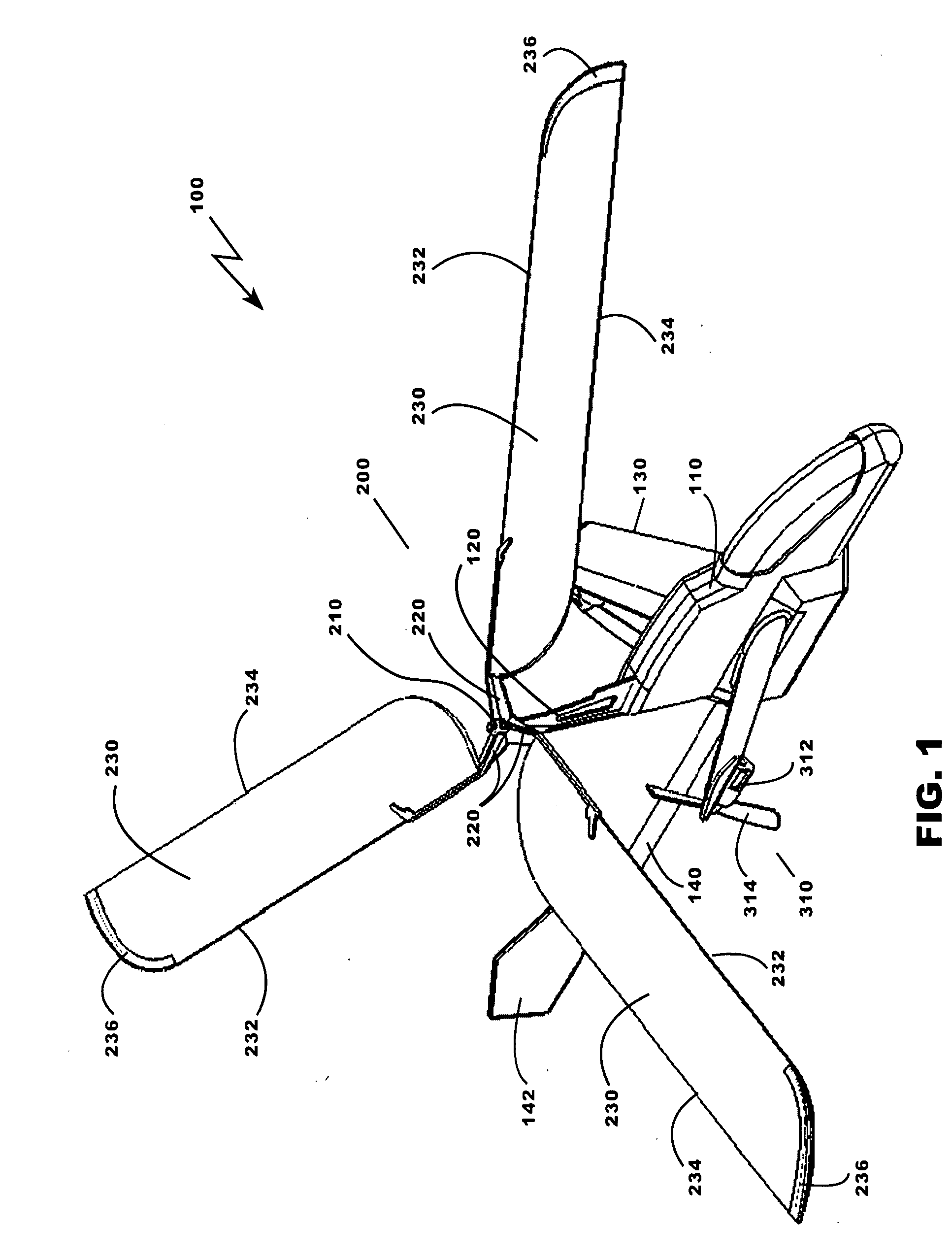
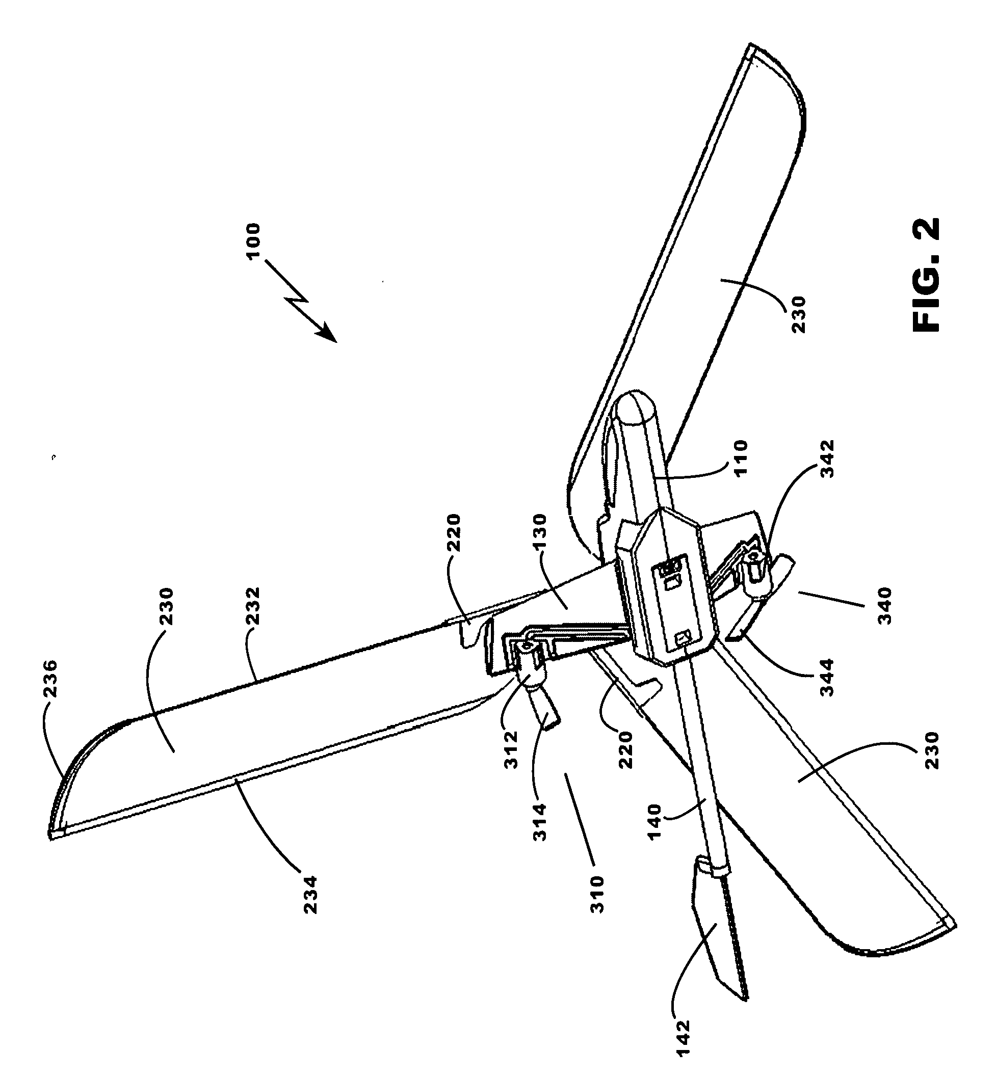
[0007]The gyro helicopter described herein seeks to overcome the above disadvantages. The gyro helicopter uses forward motion to force air up through the gyro helicopter's rotor blades, causing the blades to spin through autorotation. The spinning rotor creates the lift force necessary for flight and creates a gyroscopic force that stabilizes the entire vehicle allowing for intuitive control by a user. Gyroscopic stability of the gyro helicopter is further enhanced by blade tip weights that also act as blade tip protectors.
[0008]The rotor of the applicants' gyro helicopter is designed to allow a user to get the rotor spinning fast enough for flight while the user is standing still. The user can raise and lower the gyro helicopter by hand, in other words, “pump” the gyro helicopter, to get the rotor spinning. When the rotor is spinning fast enough to generate lift, the user simply releases the gyro helicopter. The gyro helicopter's drive means propel the gyro helicopter forward and the forward motion keeps the rotor spinning.
[0010]To provide stability, the lifting blades may comprise weights fixedly attached to their tips. Advantageously, the rotor is adapted to rotate when the downward force is applied to the blades or when the upward force is applied to the blades. The upward force is applied to the blades by lowering the gyro helicopter and the downward force is applied to the blades by raising the gyro helicopter, this lowering and raising referred to as a “pump” action. The rotors arms may be made of acrylonitrile butadiene styrene plastic (ABS). Additionally, a tail may be extended rearwardly from the aft of the fuselage, the tail including a vertical tail fin to provide improved directional stability to the gyro helicopter. Two winglets may be included, extending laterally away from opposite sides of the fuselage at a predetermined dihedral angle.

Problems solved by technology

However, getting the rotor spinning fast enough for flight has always been very difficult for these types of flying toys, usually requiring the user to walk or run with the toy to force enough air through the rotor to start it spinning fast enough to generate lift.
Stability and intuitive control while in flight have also posed problems for these toys.

Method used


Image

  • Rotary-wing miniature gyro helicopter
  • Rotary-wing miniature gyro helicopter
  • Rotary-wing miniature gyro helicopter

Examples


Embodiment Construction

[0019]The rotary-wing gyro helicopters are herein described in detail. One of the gyro helicopters generally comprises a fuselage, a rotor mast extending upwardly from the top of the fuselage, a rotor adapted to autorotate when the gyro helicopter moves forward, and drive means mounted to the fuselage for driving the gyro helicopter in at least a forward direction and for causing the gyro helicopter to perform yawing motions. The rotor of the gyro helicopter includes a hub mounted to the rotor mast, at least two rotor arms extending radially from the hub, and at least two lifting blades, the leading edge of one of the blades fixedly mounted to each of the rotor arms. The rotor arms are adapted to twist in a first direction while an upward force is applied to the blades, raising the trailing edge of the blades above the plane of the rotor, and the rotor arms are adapted to twist in a second direction while a downward force is applied to the blades, the twisting in a second direction ...


PUM


Abstract

There is provided a gyro helicopter generally comprising a fuselage, a rotor mast extending upwardly from the top of the fuselage, a rotor adapted to autorotate when the gyro helicopter moves forward, and drive means mounted to the fuselage for driving the gyro helicopter in at least a forward direction and for causing the gyro helicopter to perform yawing motions. The rotor of the gyro helicopter includes a hub mounted to the rotor mast, at least two rotor arms extending radially from the hub, and at least two corresponding lifting blades, a leading edge of each of the lifting blades fixedly mounted to a corresponding one of the rotor arms. The rotor arms are adapted to twist in a first direction while an upward force is applied to the blades, raising the trailing edge of the blades above the plane of the rotor, and the rotor arms are adapted to twist in a second direction while a downward force is applied to the blades, the twisting in a second direction lowering the trailing edge of the blades below the plane of the rotor.

Description

BACKGROUND OF THE INVENTION[0001]1. Field of the Invention[0002]This invention relates to rotary-wing vehicles and in particular to miniature, rotary-wing gyro helicopters.[0003]2. Description of the Related Art[0004]A gyro helicopter, or autogyro, is a flying machine. Like a regular helicopter, it is a rotary-wing aircraft, which means that it has a rotor to provide lift instead of wings like conventional airplanes. Unlike a regular helicopter, the rotor is not powered by an engine. The rotor is made to spin by aerodynamic forces, through a phenomenon called autorotation.[0005]Since the rotor of a gyro helicopter is not powered, a gyro helicopter needs a separate source for forward propulsion, like an airplane. Forward propulsion can be provided by, for example, propellers. When a gyro helicopter is propelled forward, air is forced up through the rotor blades, that is, through the area swept by the blades or the “rotor disk”, which starts the blades turning. The rotation of the rot...

Claims


Application Information

Patent Timeline
IPC IPC(8): B64C27/06
CPCA63H27/12
Inventor CORSIGLIA, JEFFREY JAMESSINK, CHARLES
Owner SPIN MASTER LTD
Learn More