Numerical controller controlling acceleration and deceleration of respective control axes up to command speeds

a controller and control axes technology, applied in the field of numerical controllers, can solve problems such as increasing the load applied to the connecting parts, increasing the load on the connecting parts, and the difference in the position between the control axes to gradually increase, so as to avoid abrupt speed changes, and reduce the load on the connecting parts.

Active Publication Date: 2009-01-08
FANUC LTD
View PDF2 Cites 13 Cited by
  • Summary
  • Abstract
  • Description
  • Claims
  • Application Information

AI Technical Summary

Benefits of technology

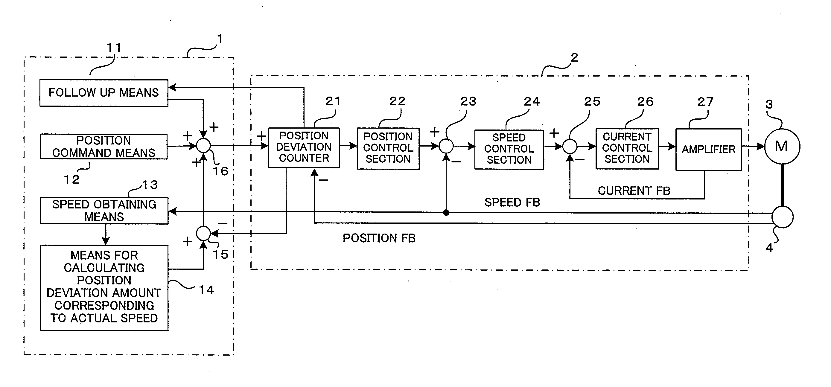
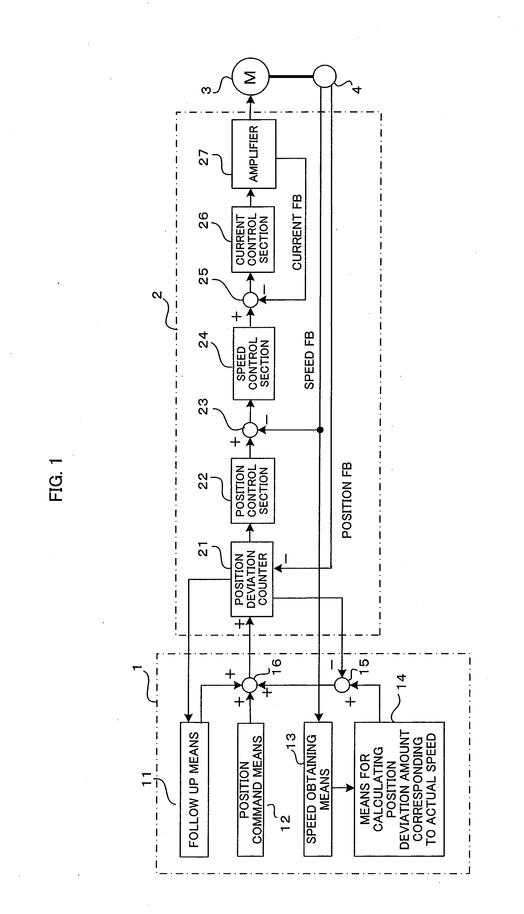
[0016]In the present invention, an optimal initial speed is determined on the basis of the difference in speed and the comparative relationship between the actual speeds of the control axes and the control axis specified at the point in time at which the servomotors are switched to the servo-on state, and the initial speeds in the move commands for the control axes are commonly set to this optimal initial speed, so the difference in position between the control axes does not increase as the move commands are executed after servo-on and the load on the connecting part can be reduced.
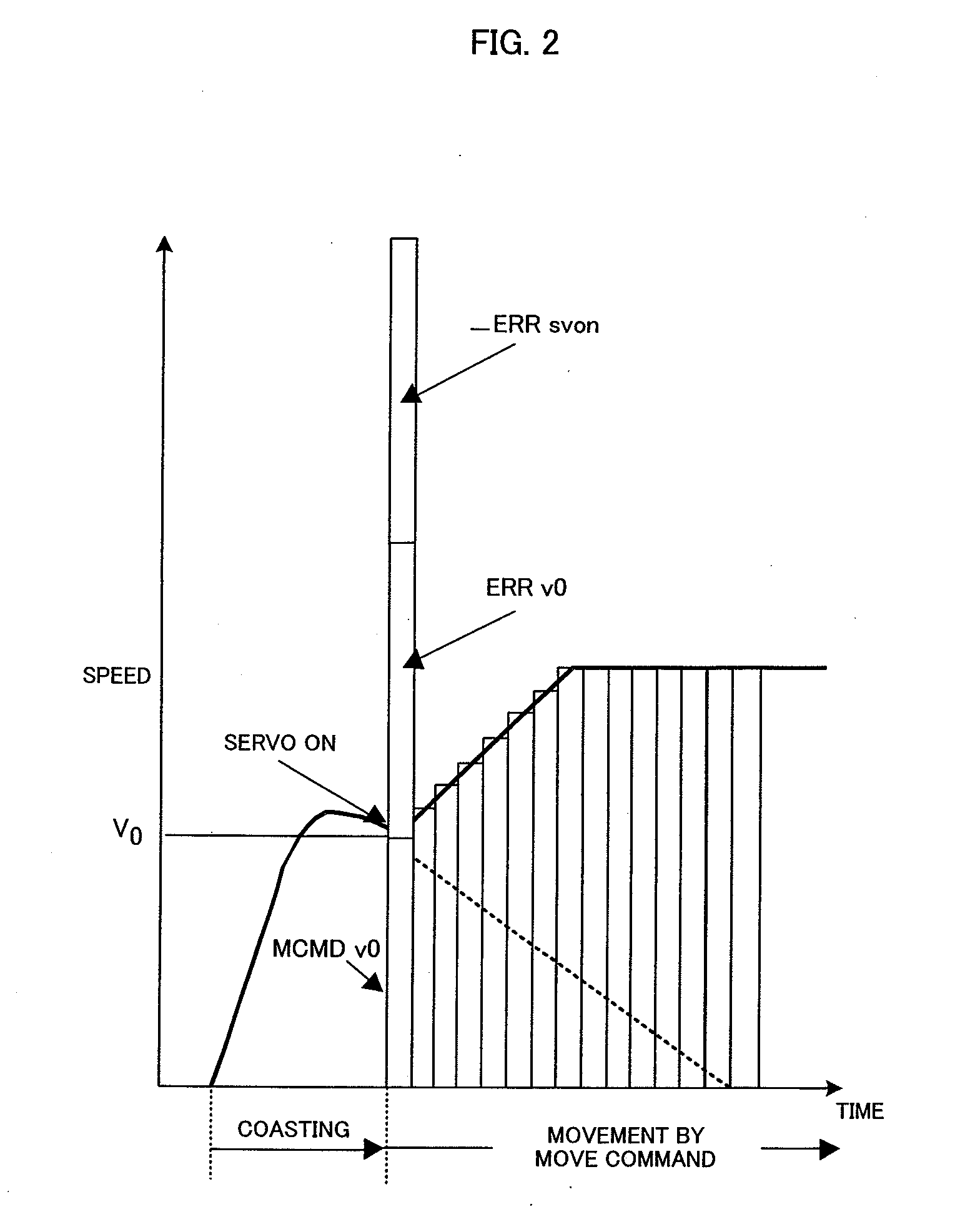
[0017]The load on the connecting part can further be reduced because the actual speeds of the control axes are set as the initial speeds in the move commands issued at servo-on, a target axis is selected on the basis of the comparative relationship between the actual speeds, and the other control axis is accelerated or decelerated at the acceleration or deceleration rates specified in the move commands to attain the position and speed of the target axis, so that the difference in position before servo-on (in the servo-off state) and after servo-on can be eliminated when the other control axis attains the position and speed of the target axis.
[0018]The differences in position and speed between the control axes gradually decrease, so abrupt speed changes can be avoided and mechanical shocks can be suppressed.

Problems solved by technology

When a plurality of servomotors are connected and operated synchronously, setting the actual speeds at servo-on of the control axes as the initial speeds in the move commands and accelerating the axes at the same acceleration rates causes the difference in position between the control axes to gradually increase and problems to arise such as increasing loads applied to the connecting parts (see FIG. 20).

Method used


Image

  • Numerical controller controlling acceleration and deceleration of respective control axes up to command speeds
  • Numerical controller controlling acceleration and deceleration of respective control axes up to command speeds
  • Numerical controller controlling acceleration and deceleration of respective control axes up to command speeds

Examples


case b (see fig.10) : vcmd > v01 and vcmd > v02 [ 0077 ] if v01 > v02 , the initial speed in the move command is v01 , [ 0078 ] if v01 = v02 , the initial speed in the move command is v01 or v02 , and [ 0079 ] if v0102 , the initial speed in the move command is v02.[ 0080 ] case c (see fig.11) : vcmd01 and vcmd02 [ 0081 ] if v01 > v02 , the initial speed in the move command is v02 , [ 0082 ] if v01 = v02 , the initial speed in the move command is v01 or v02 , and [ 0083 ] if v0102 , the initial speed in the move command is v01.[ 0084 ] case d (see fig.12)

[0075]The following Cases B through D are examples of determining the initial speed in the move command at servo-on when the servomotors drive two control axes, in which the initial speed is set on the basis of the command speed and the comparative relationship between the actual speeds of the first and second control axes at servo-on. The move commands after servo-on are issued in the format as described with reference to Case A and FIG. 9. It is assumed that the speed instructed in the move commands after servo-on is VCMD, and the actual speeds of the first and second control axes at servo-on are v01 and v02, respectively.[0076]Case B (see FIG. 10): VCMD>v01 and VCMD>v02[0077]If v01>v02, the initial speed in the move command is v01,[0078]if v01=v02, the initial speed in the move command is v01 or v02, and[0079]if v0102, the initial speed in the move command is v02.[0080]Case C (see FIG. 11): VCMD01 and VCMD02[0081]If v01>v02, the initial speed in the move command is v02,[0082]if v...


PUM

PropertyMeasurementUnit
speedaaaaaaaaaa
speedsaaaaaaaaaa
accelerationaaaaaaaaaa

Abstract

Initial speeds in the move commands for respective control axes at servo-on are determined according to parameter setting, or the comparative relationship or difference in speed among the actual speeds of the control axes so that difference in position between the control axes does not increase as the move commands are executed after the servo-on. The actual speeds of the control axes are set as initial speeds in the move commands, and a target axis is specified on the basis of the comparative relationship among their actual speeds and the other control axes are accelerated or decelerated at the acceleration or deceleration rate specified in the move commands to attain the position and speed of the target axis, so that differences in position and speed among the control axes are gradually decreased as the move commands are executed after the servo-on, thereby preventing abrupt speed changes and suppressing mechanical shocks.

Description

BACKGROUND OF THE INVENTION[0001]1. Field of the Invention[0002]The present invention relates to a numerical controller for controlling the positions of servomotors or the positions of control axes controllably driven by the servomotors, and in particular to a numerical controller that initiates positional control in a novel way by supplying current to the servomotors in a state in which no current is supplied to the servomotors and the servomotors (movable parts) are coasting.[0003]2. Description of the Related Art[0004]In die casting machines, pressing machines, and other machines in which servomotors are used to drive movable molds (control axes) to open and close the molds, a large force is required to open the molds, so it is known that current is not supplied to the servomotors (this state will be referred to hereinafter as “servo-off”) and workpieces and the movable molds are ejected from the stationary molds by a hydraulic pressure or the like, and current is then supplied t...

Claims


Application Information

Patent Timeline
Patent Type & Authority Applications(United States)
IPC IPC(8): G05B19/416
CPCG05B19/416G05B2219/42333G05B2219/50216B22D17/32G05B2219/45204G05B2219/41107G05B2219/41123G05B2219/42062G05B7/02
Inventor HISHIKAWA, TETSUOIDEI, TAKASHI
Owner FANUC LTD
Why Eureka
Try Eureka