Connector

a technology of connecting rods and connectors, applied in the direction of coupling device connections, connection contact member materials, coupling protective earth/shielding arrangements, etc., can solve the problems of connectors suffering from the problem of an increase in size, crosstalk between the pair of signal contacts, etc., to prevent the degradation of transmission

Inactive Publication Date: 2009-08-06
JAPAN AVIATION ELECTRONICS IND LTD
View PDF1 Cites 6 Cited by
  • Summary
  • Abstract
  • Description
  • Claims
  • Application Information

AI Technical Summary

Benefits of technology

[0011]The present invention has been made in view of these circumstances, and an object thereof is to p

Problems solved by technology

In the above-described arrangement of the contact portions, only the pair of signal contacts S located at a right end in the upper row are not in a state sandwiched by ground contacts G. As a result, variation in transmission characteristics is caused between the pair of signal contacts S and the other pairs of signal contacts, and there is a fear that crosstalk may occur between the pair of signal contacts S and other pairs of signal contacts loc

Method used


Image

  • Connector
  • Connector
  • Connector

Examples


second embodiment

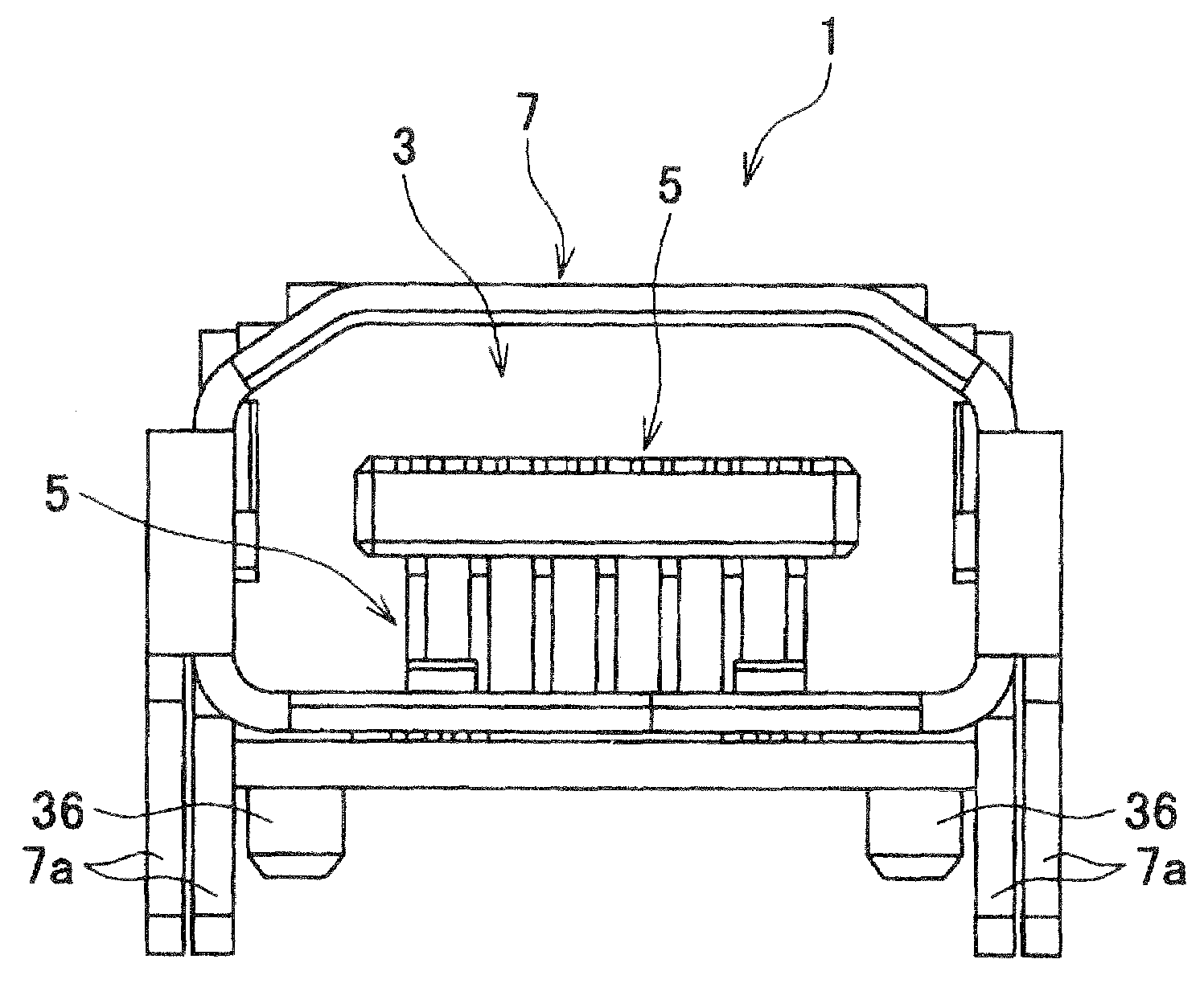
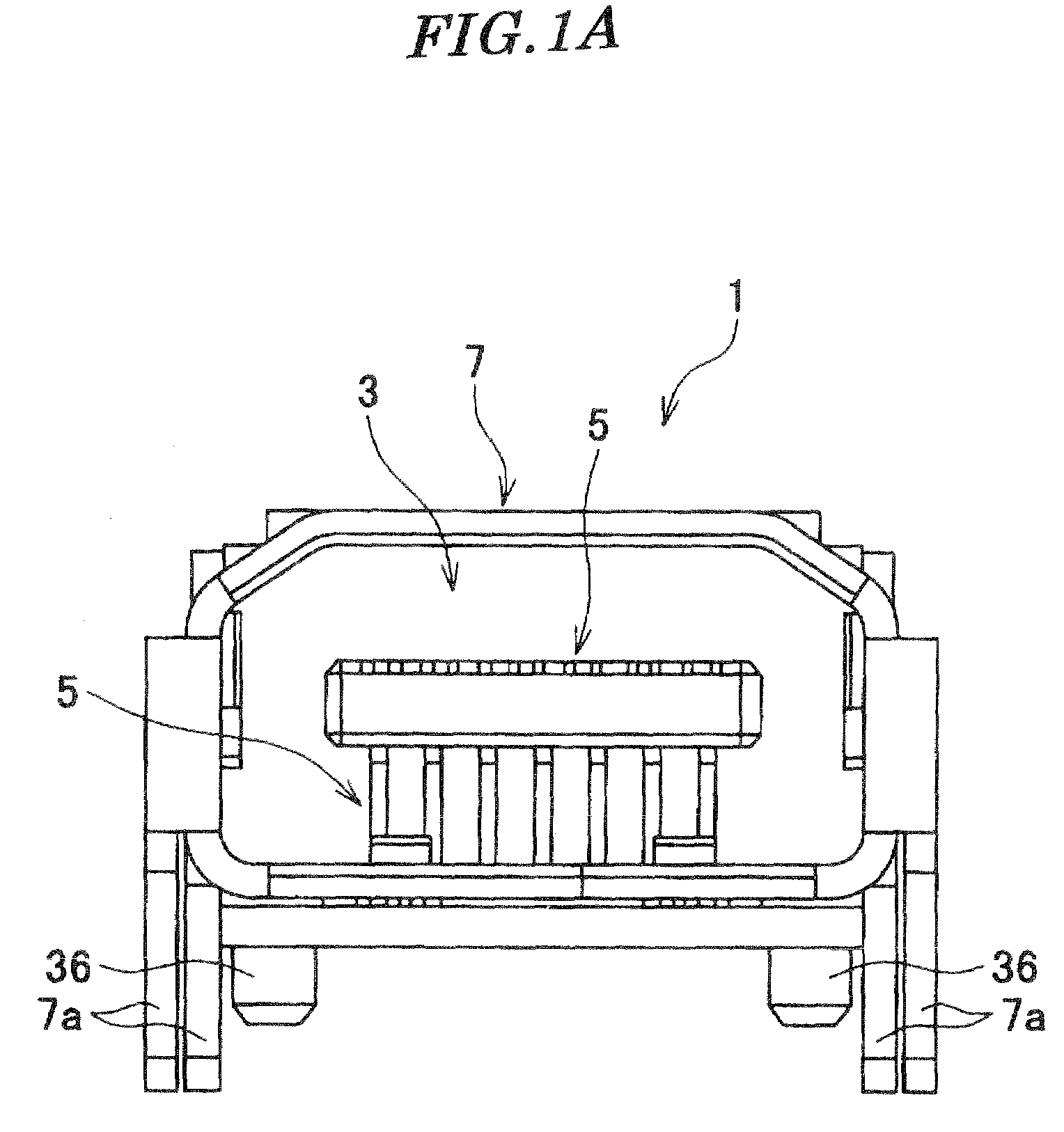
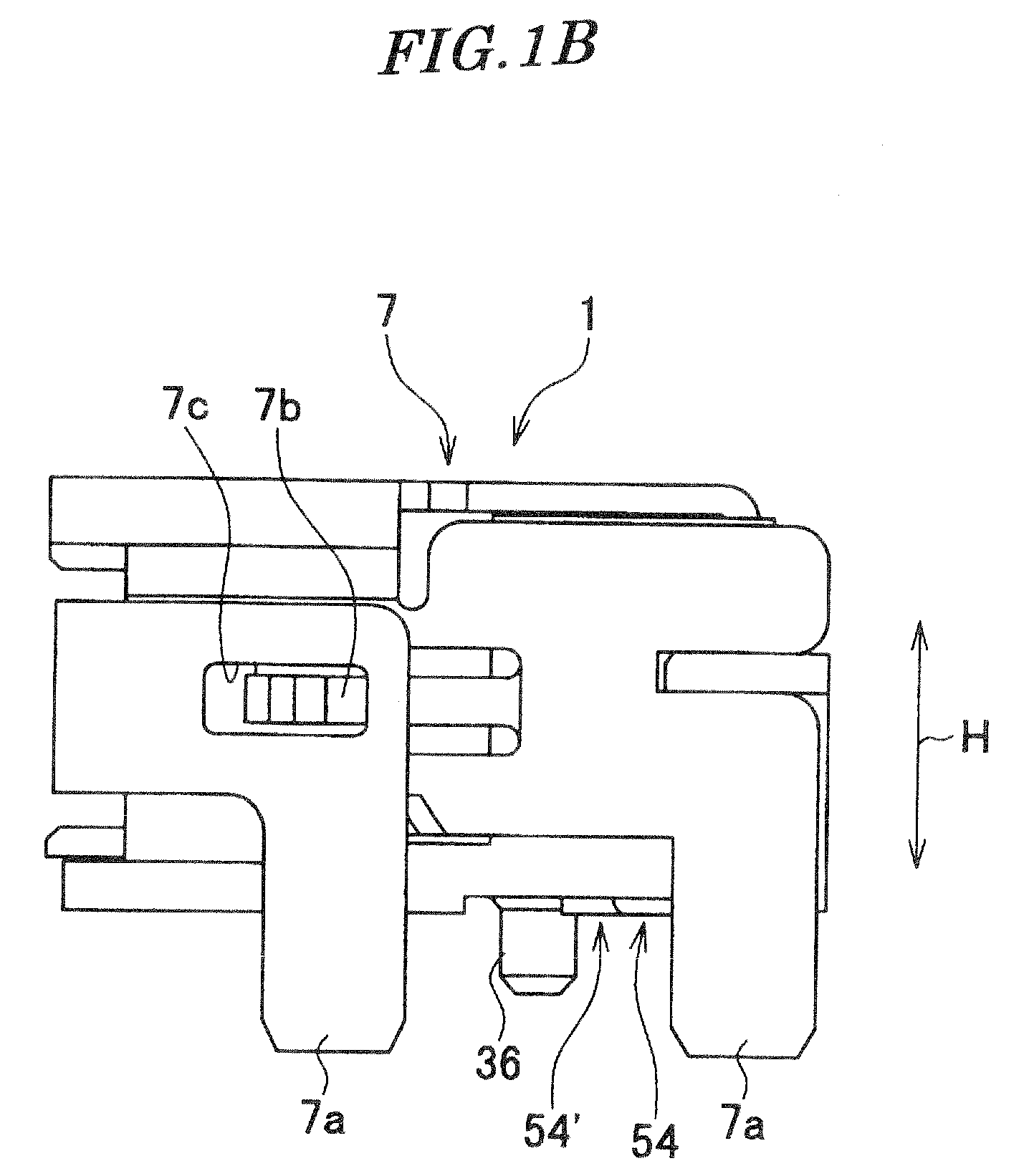
[0051]FIG. 5A is a front view of a connector according to the present invention, and FIG. 5B is a side view of the connector. FIG. 6 is a cross-sectional view of part of the connector shown in FIG. 5A.

first embodiment

[0052]The connector 201 is the mating connector of the connector 1 according to the

[0053]Although in the connector 1, each of the first and second signal contacts 51 and 52, the ground contacts 53, and the contacts 54 and 54′ for non-high speed transmission is bent into L-shape, in the connector 201, each of first and second signal contacts 251 and 252, ground contacts 253, and contacts 254 and 254′ for non-high speed transmission has a linear shape.

[0054]Although in the connector 1, each of the terminal portions (connection portion) 51d, 52d, 53d, 54d, and 54d′ of the respective contacts 51, 52, 53, 54, and 54′ has a shape for being mounted on the printed board, in the connector 201, each of wiring portions (terminal portions), not shown, of respective contacts 251, 252, 253, 254, and 254′ has a shape which is capable of being connected to cables.

[0055]Although in the connector 1, the terminal portions 54d and 54′d of the contacts 54 and 54′ for non-high-speed transmission are in s...


PUM


Abstract

A connector which is capable of preventing degradation of transmission, and achieving downsizing. Contact portions of first and second signal contacts, and contact portions of ground contacts are arranged in a row in a contact arranging direction. Contact portions of contacts for non-high-speed transmission are arranged in a row in the contact arranging direction. The row formed by the contact portions of the first and second signal contacts, and the contact portions of the ground contacts, and the rows formed by the contact portions of the contacts for non-high-speed transmission are parallel. The contact portions of each pair of first and second signal contacts are disposed between the contact portions of adjacent ones of the ground contacts in the contact arranging direction.

Description

BACKGROUND OF THE INVENTION[0001]1. Field of the Invention[0002]This invention relates to a connector, more particularly to a connector which is suitable for high-speed transmission of electric signals.[0003]2. Description of the Related Art[0004]Conventionally, there has been proposed a receptacle connector comprised of three types of contacts, an insulator for holding the contacts, and a receptacle shell for covering the insulator (see Japanese Laid-Open Patent Publication (Kokai) No. 2002-334748).[0005]The three types of contacts include a signal contact S and a ground contact G for high-speed transmission, and a contact D for non-high-speed transmission. Each of the three types of contacts has contact portions which are capable of being brought into contact with contact portions of mating contacts of a mating connector, and terminal portions which are capable of being soldered to pads on a printed board.[0006]The contact portions are arranged in two rows, one above the other (se...

Claims


Application Information

Patent Timeline
IPC IPC(8): H01R13/648H01R24/00
CPCH01R13/6471
Inventor TANAKA, YUKITAKA
Owner JAPAN AVIATION ELECTRONICS IND LTD
Why Eureka
Try Eureka