Flow rate control mechanism and gas chromatograph including flow rate control mechanism

Active Publication Date: 2015-12-03
SHIMADZU CORP
View PDF7 Cites 6 Cited by
  • Summary
  • Abstract
  • Description
  • Claims
  • Application Information

AI Technical Summary

Benefits of technology

[0017]The flow rate control mechanism which controls the flow rate of carrier gas is fashioned as a single block, so the number of channel connection parts to be sealed with O-rings is greatly reduced.
[0018]The second gas chromatograph pertaining to the present invention is characterized in that the flow rate control mechanism of the present invention is interposed between the detector gas supply source and a channel of the detector gas supply unit for supplying detector gas to the detector, which channel communicates with the detector. Just as in the case of the flow rate control mechanism which controls the supply rate of carrier gas of the first gas chromatograph described above, the flow rate control mechanism which controls the supply rate of detector gas here is fashioned as a single block, so the number of channel connection parts to be sealed with an O-ring is greatly reduced.
[0019]The flow rate control mechanism of the

Problems solved by technology

While air-tightness of the connections between component parts and channels is maintained with O-rings made of fluorine rubber or the like, there is the possibility that the gas which is inside will leak from these connections, or that outside air or impurities will become admixed into the channel

Method used


Image

  • Flow rate control mechanism and gas chromatograph including flow rate control mechanism
  • Flow rate control mechanism and gas chromatograph including flow rate control mechanism
  • Flow rate control mechanism and gas chromatograph including flow rate control mechanism

Examples


Embodiment Construction

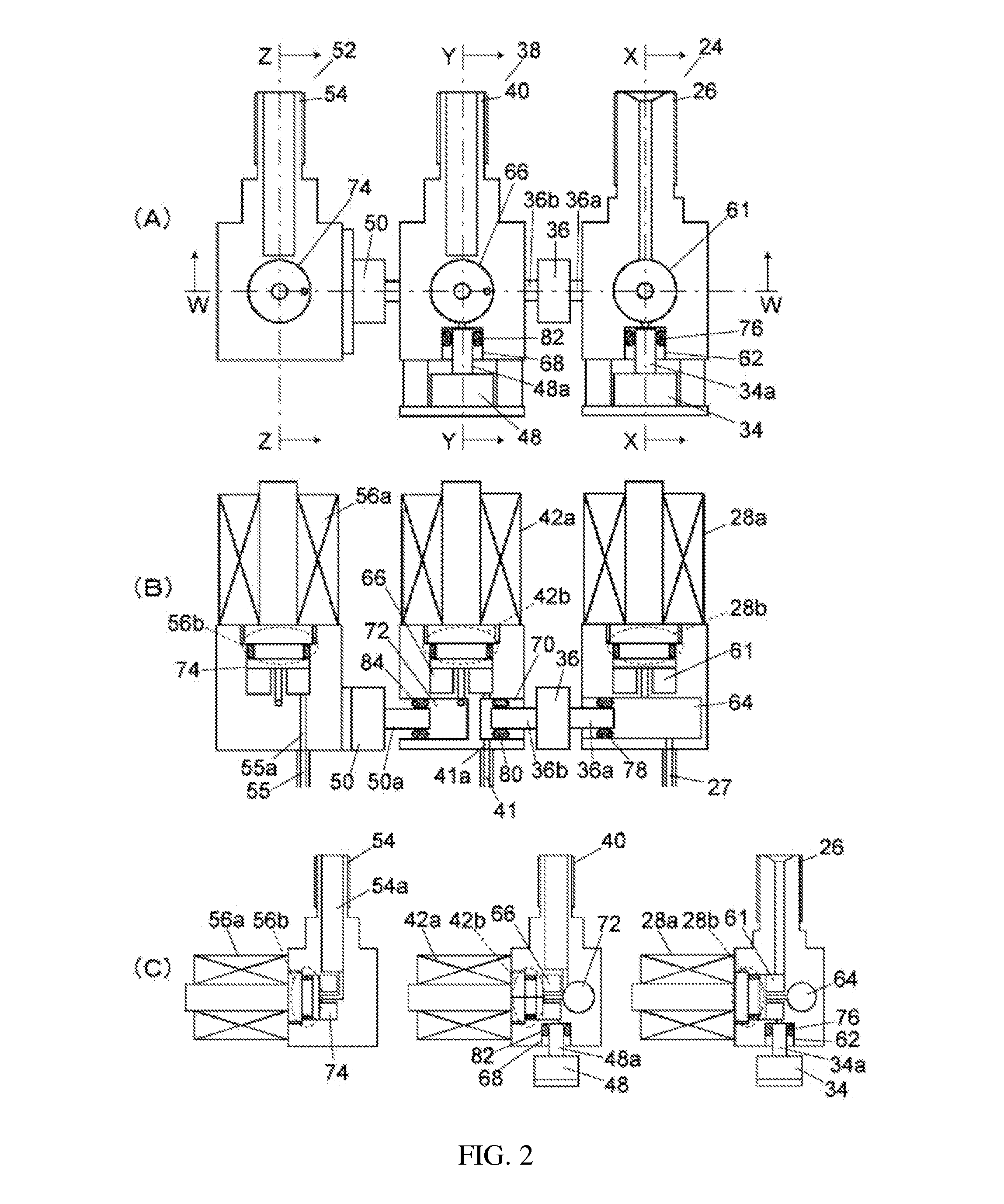
[0026]In a preferable example of embodiment of the present invention, within the block, there is further provided a sensor connection channel whereof one end communicates with the internal channel and which serves for connecting a pressure sensor to the internal channel. Conventionally, when connecting a pressure sensor to a channel through which gas flows, it was necessary to connect the pressure sensor via a connection block to the channel through which gas flows, so the number of channel connection parts using a sealing member such as an O-ring would further increase. By contrast, by making it possible to directly connect the pressure sensor to the block of the flow rate control mechanism of the present invention by providing a channel for connecting the pressure sensor, the increase in the number of channel connection parts using a sealing member such as an O-ring can be kept to a minimum.

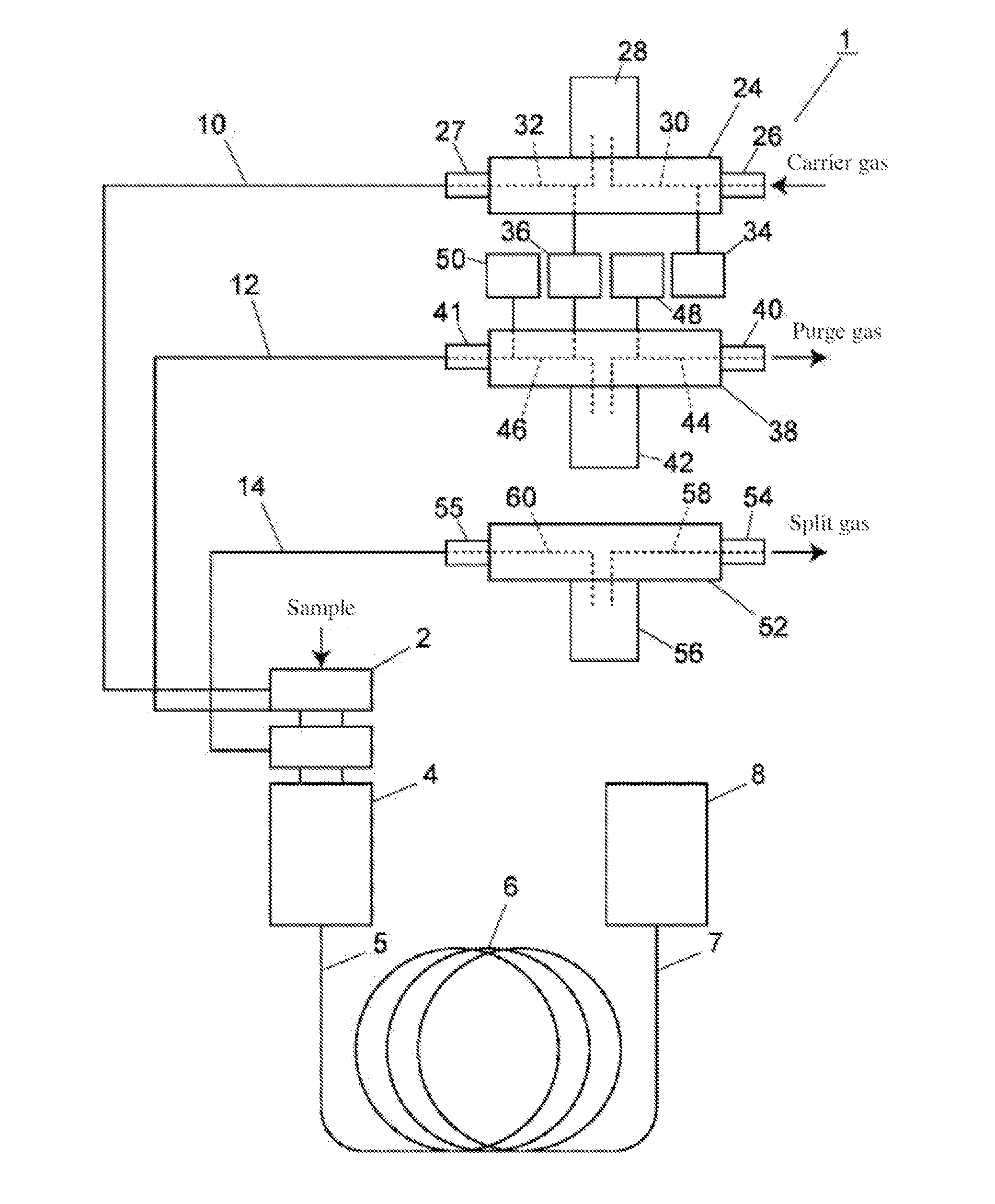
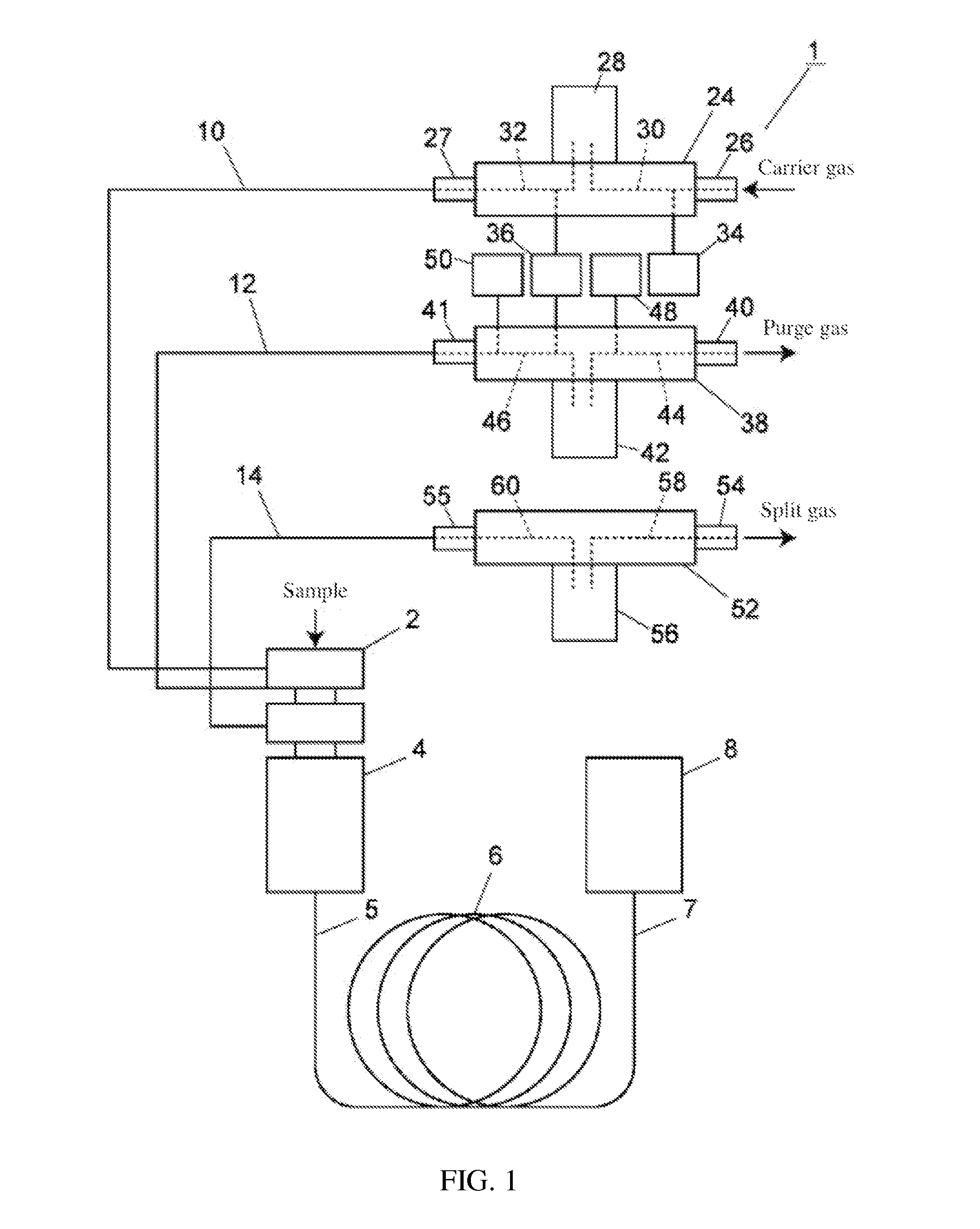
[0027]An example of embodiment of a gas chromatograph will be described below using FIG. 1....


PUM


Abstract

One end of carrier gas channel, purge gas channel and split gas channel is connected to sample gasification chamber. The other end of carrier gas channel, purge gas channel, and split gas channel is connected to a flow rate control mechanism in the form of carrier gas flow rate control block, purge gas flow rate control block and split gas flow rate control block respectively. Carrier gas flow rate control block, purge gas flow rate control block and split gas flow rate control block constitute a flow rate control unit. This reduces the possibility of leakage of gas to the outside and admixture of impurities from the outside in the flow rate control mechanism.

Description

[0001]This application incorporates by reference Japan Patent Publication No. 2013-124673, published Jun. 24, 2013 to the same inventors.TECHNICAL FIELD[0002]The present invention relates to a flow rate control mechanism which is interposed between a gas supply source and a gas channel which guides the gas to a predetermined part, in order to control the gas flow rate; the invention also relates to a gas chromatograph comprising said flow rate control mechanism.BACKGROUND ART[0003]Gas chromatographs comprise an analytical column, a sample introduction channel for guiding the sample to the analytical column, a sample injection unit for injecting the sample into the sample introduction channel, a carrier gas supply unit for supplying carrier gas to the sample injection unit, and a detector (for example, see Patent literature 1). The sample is injected from the sample introduction unit and is conveyed to the analytical column by the carrier gas supplied from the carrier gas supply unit...

Claims


Application Information

Patent Timeline
IPC IPC(8): G01N30/32G01N30/16F16K7/02
CPCG01N30/32F16K7/02G01N2030/324G01N2030/025G01N30/16G01N30/10G01N30/68
Inventor TERAI, YASUNORI
Owner SHIMADZU CORP
Why Eureka
Try Eureka