Line driver capable of automatically adjusting output impedance

Active Publication Date: 2009-01-08
REALTEK SEMICON CORP
View PDF5 Cites 3 Cited by
  • Summary
  • Abstract
  • Description
  • Claims
  • Application Information

AI Technical Summary

Benefits of technology

[0015]The line driver of this invention comprises: a differential amplifier for amplifying an input signal to generate an output signal, the differential amplifier including an inverting input terminal, a non-inverting input terminal, an inverting output terminal, and a non-inverting output terminal, the inverting input terminal and the non-inverting input terminal receiving the input signal; first and second series resistors, the first series resistor being coupled to the non-inverting output terminal of the differential amplifier, the second series resistor being coupled to the inverting output terminal of the differential amplifier, the output signal generated by the differential amplifier being output through the first and second series resistors; first and second negative-feedback resistors, the first negative-feedback resistor being coupled between th

Problems solved by technology

More space is required to implement such large switches.

Method used


Image

  • Line driver capable of automatically adjusting output impedance
  • Line driver capable of automatically adjusting output impedance
  • Line driver capable of automatically adjusting output impedance

Examples


Embodiment Construction

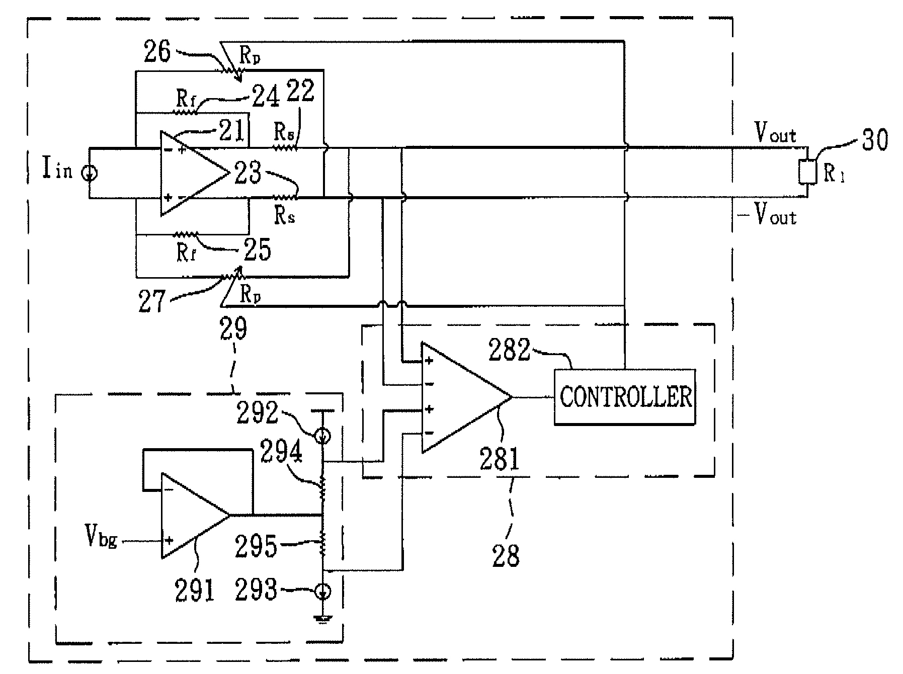
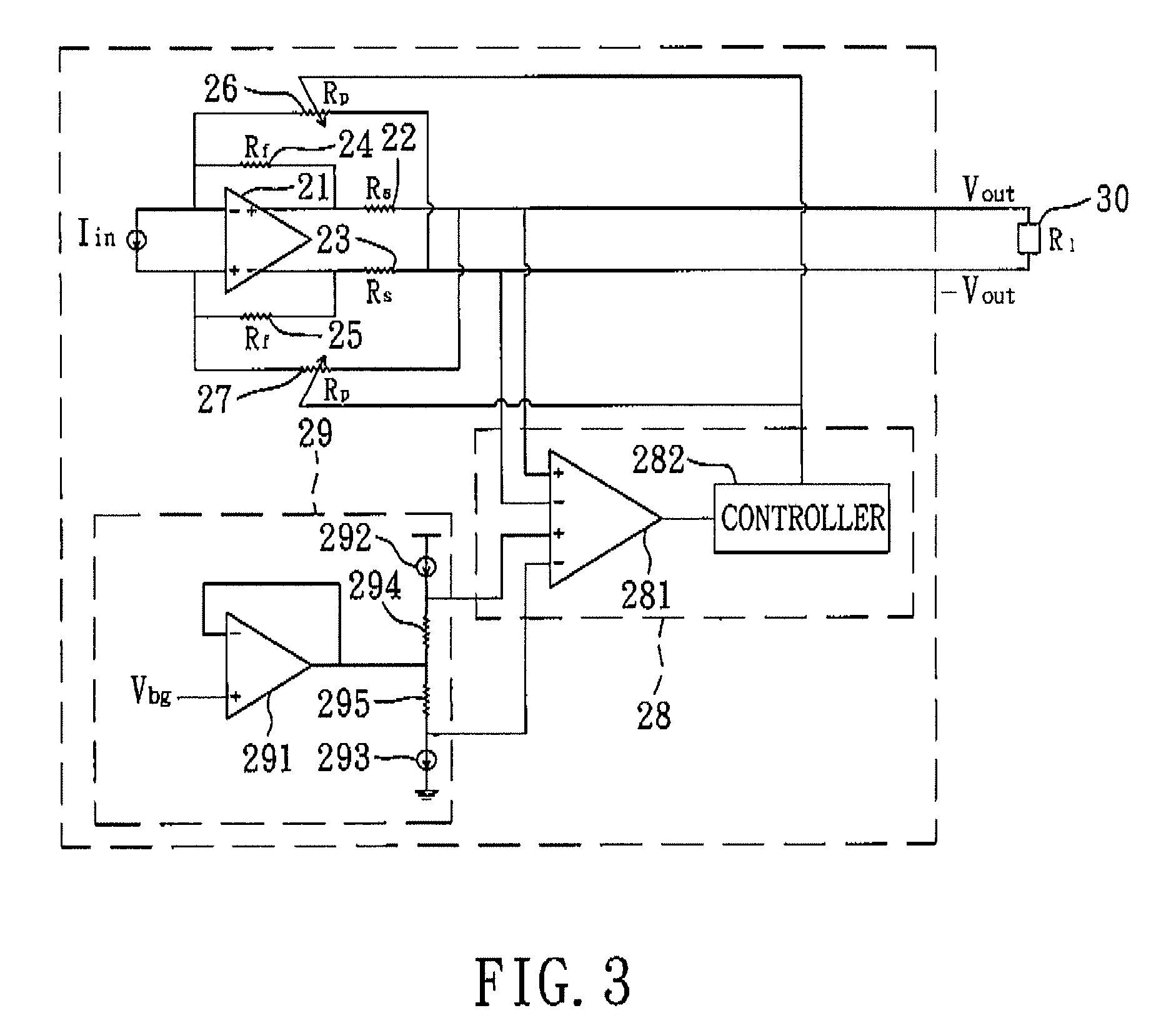
[0021]Referring to FIG. 3, a line driver according to a first preferred embodiment of the present invention is adapted to form part of an integrated circuit (not shown), and is further adapted to be coupled to a load 30 that is external to the integrated circuit and that has a load resistance (R1). The line driver of the first preferred embodiment comprises a differential amplifier 21, a series resistor unit including first and second series resistors 22, 23, a negative-feedback resistor unit including first and second negative-feedback resistors 24, 25, a positive-feedback variable resistor unit including first and second positive-feedback variable resistors 26, 27, and an adjusting unit 28. Each of the first and second positive-feedback variable resistors 26, 27 includes a plurality of resistor elements (not shown) and a plurality of switches (not shown). The switches may be controlled to vary coupling states of the resistor elements and thereby vary a resistance (Rp) of each of t...


PUM


Abstract

A line driver includes: a differential amplifier for amplifying an input signal to generate an output signal; first and second series resistors coupled respectively to output terminals of the differential amplifier and through which the output signal is output; first and second negative-feedback resistors each coupled between a respective input terminal and a respective output terminal of the differential amplifier; first and second positive-feedback variable resistors each coupled between a respective input terminal of the differential amplifier and a respective one of the first and second series resistors; and an adjusting unit coupled to the first and second positive-feedback variable resistors to adjust a resistance thereof with reference to the output signal.

Description

CROSS-REFERENCE TO RELATED APPLICATION[0001]This application claims priority of Taiwanese Application No. 096124752, filed on Jul. 6, 2007.BACKGROUND OF THE INVENTION[0002]1. Field of the Invention[0003]The present invention relates to a line driver, more particularly to a line driver that is capable of automatically adjusting an output impedance.[0004]2. Description of the Related Art[0005]A transmission line is used to transmit high-speed signals, and a line driver is used to drive the input to the transmission line with a higher than normal signal level. However, in order to reduce signal reflection, an output impedance of the line driver must be matched with a characteristic impedance of the transmission line.[0006]FIG. 1 shows a conventional active terminal line driver which forms a part of an integrated circuit (not shown). The line driver is coupled to a load 18 that has a resistance (R1). The line driver is used to amplify an input current (Iin) to produce an output voltage ...

Claims


Application Information

Patent Timeline
IPC IPC(8): H03F1/36
CPCH03F1/34H03F3/45475H03F2203/45528H03F2203/45522H03F2203/45138
Inventor LIAO, SU-LIANGCHIANG, MING-CHENG
Owner REALTEK SEMICON CORP
Why Eureka
Try Eureka