Surface Emitting Device and Liquid Crystal Display

a surface emitting device and liquid crystal display technology, applied in lighting device details, lighting and heating apparatuses, instruments, etc., can solve the problems of large size, lack of luminance of edge-lighting backlight units, etc., to improve luminance uniformity and increase the number of light-source images

Inactive Publication Date: 2009-01-08
THOMSON LICENSING SA
View PDF4 Cites 7 Cited by
  • Summary
  • Abstract
  • Description
  • Claims
  • Application Information

AI Technical Summary

Benefits of technology

[0011]The above-described method of dividing the light-source image using the prism sheet 6 needs to divide the light-source image into two main images at a short interval so as to distribute the luminance uniformly in an efficient manner.
[0014]The present invention is made in view of the above problems. Accordingly, an object of the invention is to provide a surface emitting device in which the number of divisions of the main light-source image is increased to enhance the uniformity of luminance distribution and a liquid crystal display having the same.
[0017]According to the invention, the light-source-image division sheet has a flat portion parallel to the sheet surface between the adjacent linear, conical, or pyramidal protrusions or at part of the protrusions. This generates light-source images through the flat portions in addition to the divided light-source images through the linear protrusions to increase the number of light-source images, thereby improving luminance uniformity. Accordingly, the use of the surface emitting device as the backlight for a liquid crystal display or the like prevents unevenness in the luminance of images, thereby improving the image quality.
[0022]The surface emitting device and the display unit of the invention have a flat portion, which is parallel to the light-source-image division sheet, at least at one of the portion between the adjacent linear, conical, or pyramidal protrusions and part of the protrusions. This generates light-source images through the flat portions in addition to the divided light-source images through the linear protrusions to increase the number of light-source images, thereby improving luminance uniformity.

Problems solved by technology

However, such edge-lighting backlight units often become lacking in luminance as displays are becoming larger in size in recent years.

Method used


Image

  • Surface Emitting Device and Liquid Crystal Display
  • Surface Emitting Device and Liquid Crystal Display
  • Surface Emitting Device and Liquid Crystal Display

Examples


first embodiment

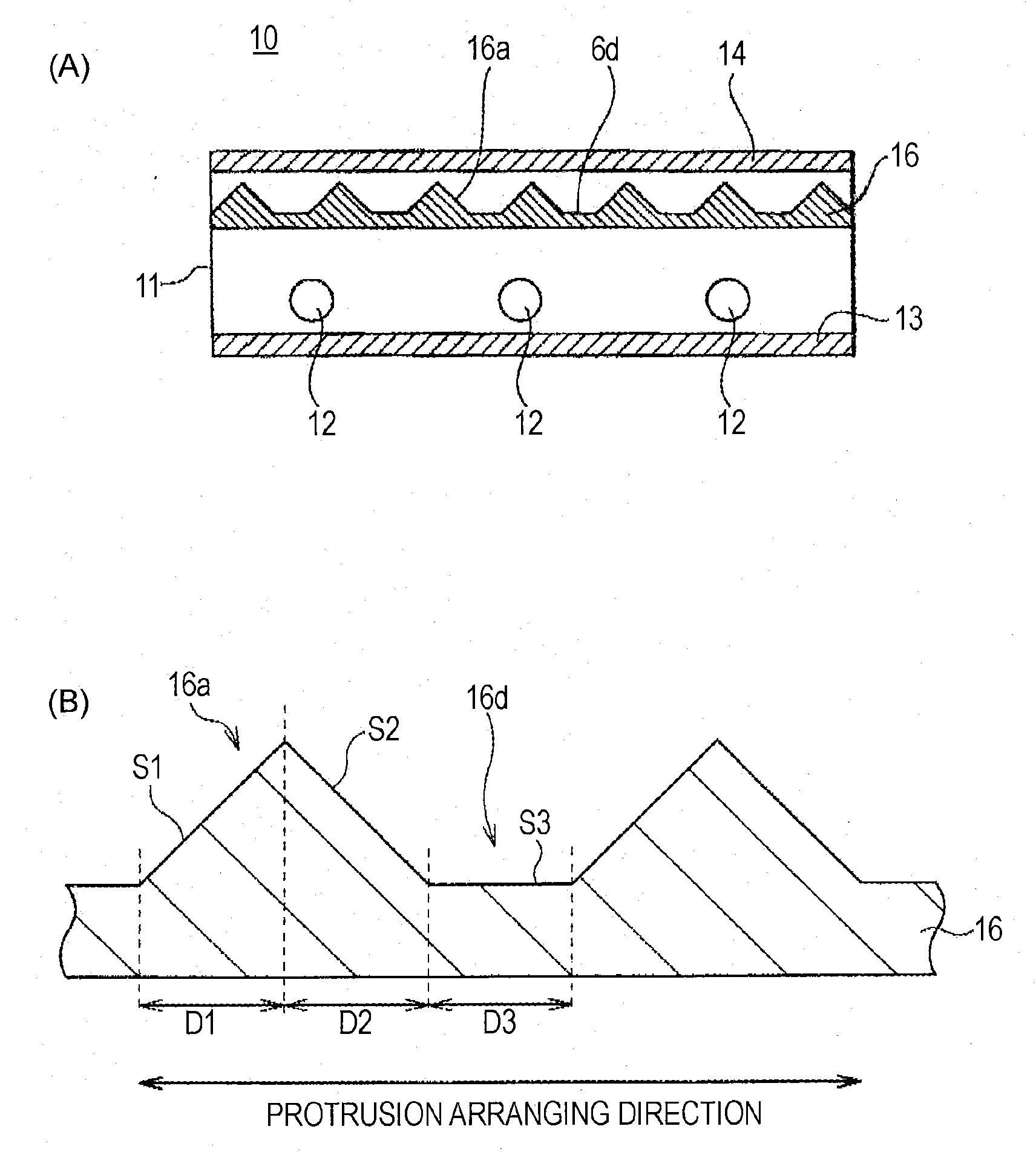
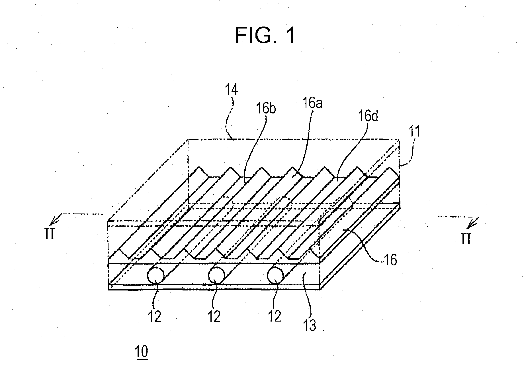
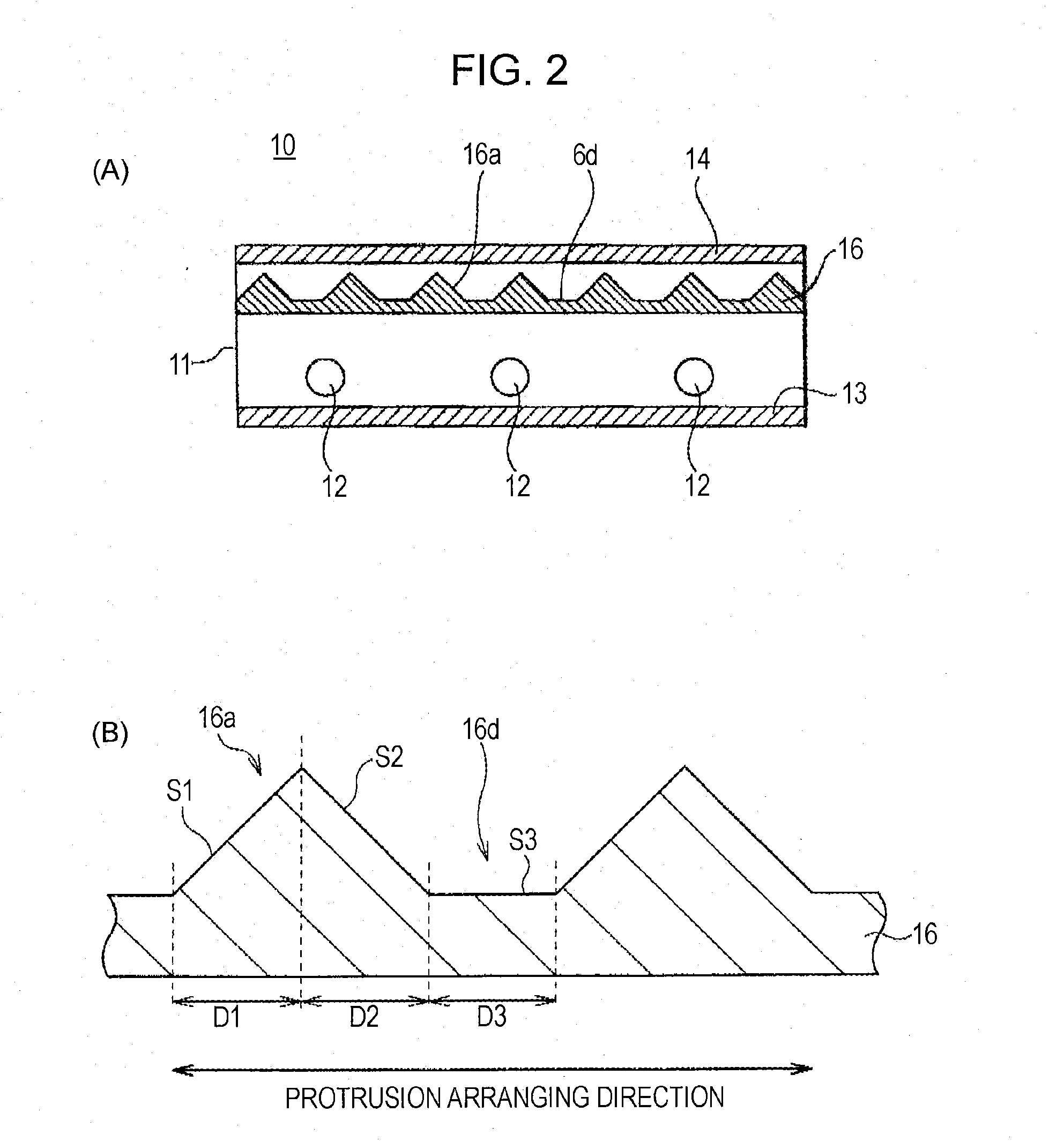
[0039]FIG. 1 is a schematic perspective view of a surface emitting device 10 according to a first embodiment of the invention; FIG. 2(A) is a cross-sectional view of the surface emitting device 10 taken along line II-II of FIG. 1; and FIG. 2(B) is a cross-sectional view of a prism sheet 16. The surface emitting device 10 is a direct-lighting type backlight unit for a liquid crystal display, for example.

[0040]The surface emitting device 10 of this embodiment includes line light sources 12, a reflector 13, a diffusing sheet 14 composed of a diffuser or a diffusion sheet, a prism sheet 16 serving as a light-source-image division sheet, and a casing 11 for housing them. The reflector 13 and the diffusing sheet 14 are disposed in opposed positions, between which a plurality of line light sources 12 is disposed in parallel at regular pitches.

[0041]The line light source 12 may be a known light source, e.g., a fluorescent tube such as a cold-cathode tube or a hot-cathode tube. The reflector...

second embodiment

[0063]FIG. 8 is a schematic perspective view of a surface emitting device 20 according to a second embodiment of the invention. The components of FIG. 8 corresponding to those of the first embodiment will be given the same numerals and their detailed description will be omitted.

[0064]The surface emitting device 20 of this embodiment includes point light sources 22, a reflector 13, a diffusing sheet 14 composed of a diffuser or a diffusion sheet, a prism sheet 16 serving as a light-source-image division sheet, and a casing 11 for housing them. The reflector 13 and the diffusing sheet 14 are disposed in opposed positions, between which a plurality of linearly arranged point light sources 22 are disposed in lines.

[0065]The prism sheet 16 has the same structure as the first embodiment, in which the edge lines 16b of the prism-shaped linear protrusions 16a are in parallel to the direction of the arrangement of the point light sources 22. Alternatively, the edge lines of the prism sheet 1...

example 1

[0069]The uniformity of luminance of the surface emitting device according to the first embodiment was tested under the following conditions. The results are shown in FIG. 9.[0070]Diffusing sheet 14: diffusion sheet D114 (manufactured by Tsujiden KK)[0071]Line light source 12 and Reflector 13: liquid crystal TV KDL-S19A10 (manufactured by Sony Corporation)[0072]Prism sheet 16: flat portion 16d: 15 μm in width[0073]linear protrusion 16a: prism with a base of 50 μm and a vertical angle of 90°[0074]Distance from line light source 12 to prism sheet 16: 7 mm[0075]Luminance meter: RISA-COLOR (manufactured by Highland)

[0076]The prism sheet 26 was manufactured in the following way:

[0077]A metal plate for hot pressing was used as an original plate in which an isosceles right-angled triangle in cross section with a vertical angle of 90°, a base of 50 μm, and a height of 25 μm and a flat portion with a width of 15 μm are continuously and alternately engraved. Thermoplastic resin, a polycarbona...


PUM

PropertyMeasurementUnit
fixed angleaaaaaaaaaa
base angleaaaaaaaaaa

Abstract

To provide a surface emitting device and a liquid crystal display in which the number of divided main light-source images is increased to enhance the uniformity of luminance distribution. A surface emitting device 10 according to the invention includes: a diffusing sheet 14 constituting a light exiting surface; a reflector 13 disposed opposite to the diffusing sheet 14; light sources 12 disposed between the diffusing sheet 14 and the reflector 13; and a prism sheet (light-source-image division sheet) 16 disposed between the diffusing sheet 14 and the light sources 12. The prism sheet 16 has linear protrusions 16a on the front surface thereof; and a flat portion 16d parallel to the sheet surface between the adjacent linear protrusions 16a. This generates light-source images through the flat portions 16d in addition to the divided light-source images through the linear protrusions 16a to increase the number of light-source images, thereby improving luminance uniformity.

Description

TECHNICAL FIELD[0001]The present invention relates to a surface emitting device suitable for use as a direct-lighting backlight unit of a liquid crystal display or the like and a liquid crystal display including the same.BACKGROUND ART[0002]Liquid crystal displays having a low-profile and easily viewable backlight (surface emitting device) have been used as displays of word processors, laptop personal computers and so on. To meet the need for such lightweight and low-profile backlights for liquid crystal displays, edge-lighting type backlight units have been mainstream in which a line light source such as a fluorescent tube is disposed at the side end of a transparent plate (light guide), and a liquid-crystal display panel is disposed on the light guide with a light diffusing sheet or the like in between.[0003]However, such edge-lighting backlight units often become lacking in luminance as displays are becoming larger in size in recent years. Therefore, direct-lighting type backligh...

Claims


Application Information

Patent Timeline
Patent Type & Authority Applications(United States)
IPC IPC(8): G02F1/1335F21V7/04
CPCG02B5/02G02F2001/133607G02F1/133604G02B5/045G02F1/133607G02F1/1335
Inventor OBATA, KEIHOSHI, MITSUNARI
Owner THOMSON LICENSING SA
Why Eureka
Try Eureka