Polarizer and display device including polarizer

a technology of polarizer and display device, which is applied in the direction of polarising elements, instruments, coatings, etc., can solve the problems of difficulty in realizing a polarizer having a wire grid structure with a sufficient ratio of transmittance tsub>p /sub>, transmittance tsub>c/sub>, etc., to achieve the effect of improving mechanical strength and improving optical properties of the polarizer

Active Publication Date: 2009-01-08
SEMICON ENERGY LAB CO LTD
View PDF13 Cites 40 Cited by
  • Summary
  • Abstract
  • Description
  • Claims
  • Application Information

AI Technical Summary

Benefits of technology

[0043]Further, in the above structure, cross-sectional shape of the first group of metal wires and the second group of metal wires, which are perpendicular to the long-side direction of the metal wires, is not limited to a rectangular shape, and they may have another shape, for example, a triangle shape or the like. Further, as the area of the light-transmitting members in the cross sections perpendicular to the long-side direction of the first group of metal wires is smaller, optical properties of the polarizer are improved; therefore, the cross-sectional shape of the light-transmitting members is desirably a rectangular shape with a narrower width than the cross-sectional shape of the second group of metal wires. Further, cross-sectional shape of the light-transmitting members perpendicular to the long-side direction of the first group of metal wires is a trapezoidal shape to stably support the second group of metal wires.
[0044]Further, the light-transmitting members may be provided to cover the metal wires for more stably supporting the metal wires to further increase mechanical strength.

Problems solved by technology

The above results show that even when the width L and spacing S are controlled, it is difficult to realize a polarizer having a wire grid structure with a sufficient ratio of transmittance TP and transmittance TC.

Method used


Image

  • Polarizer and display device including polarizer
  • Polarizer and display device including polarizer
  • Polarizer and display device including polarizer

Examples


embodiment mode 1

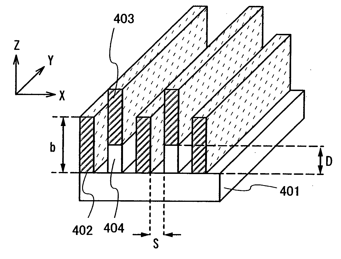
[0069]FIG. 4A and FIG. 4B illustrate an example of a polarizer having a wire grid structure of the present invention. A manufacturing method of the polarizer will be described below. FIG. 4A is a cross-sectional view taken perpendicular to a substrate surface, and FIG. 4B is a perspective view corresponding to the diagram in FIG. 4A.

[0070]First, a light-transmitting substrate 401 is prepared. A light-transmitting material such as glass, ceramics, or a resin can be used for the light-transmitting substrate 401. Further, a high refractive index glass substrate of which refractive index is controlled by controlling impurities in glass can be used for the light-transmitting substrate 401.

[0071]Next, a wire grid structure is formed over the light-transmitting substrate 401. The wire grid structure shown in FIG. 4A and FIG. 4B may be formed by suitably using a nanoimprint method such as a photo nanoimprint method or a thermal nanoimprint method; a photolithography method; an E-beam lithog...

embodiment mode 2

[0077]FIG. 6 illustrates another example of a polarizer having a wire grid structure of the present invention. In this embodiment mode, a polarizer is provided in which a first group of metal wires 602 and a second group of metal wires 603 are covered with a light-transmitting member 604 in order to increase mechanical strength of the wire grid structure. The second group of metal wires 603 have their centers in different arrangement from the centers of the first group of metal wires 602. The centers here refer to the centers of the cross sections taken in the short-side direction of the metal wires, which are perpendicular to the long-side direction thereof, that is, the width direction of the metal wires. For example, in the case where the cross-sections have a quadrangular shape, intersection points of the two lines connecting opposite corners may be a center. Further, the line connecting the centers of plural cross sections of one metal wire can be called a central axis, which i...

embodiment mode 3

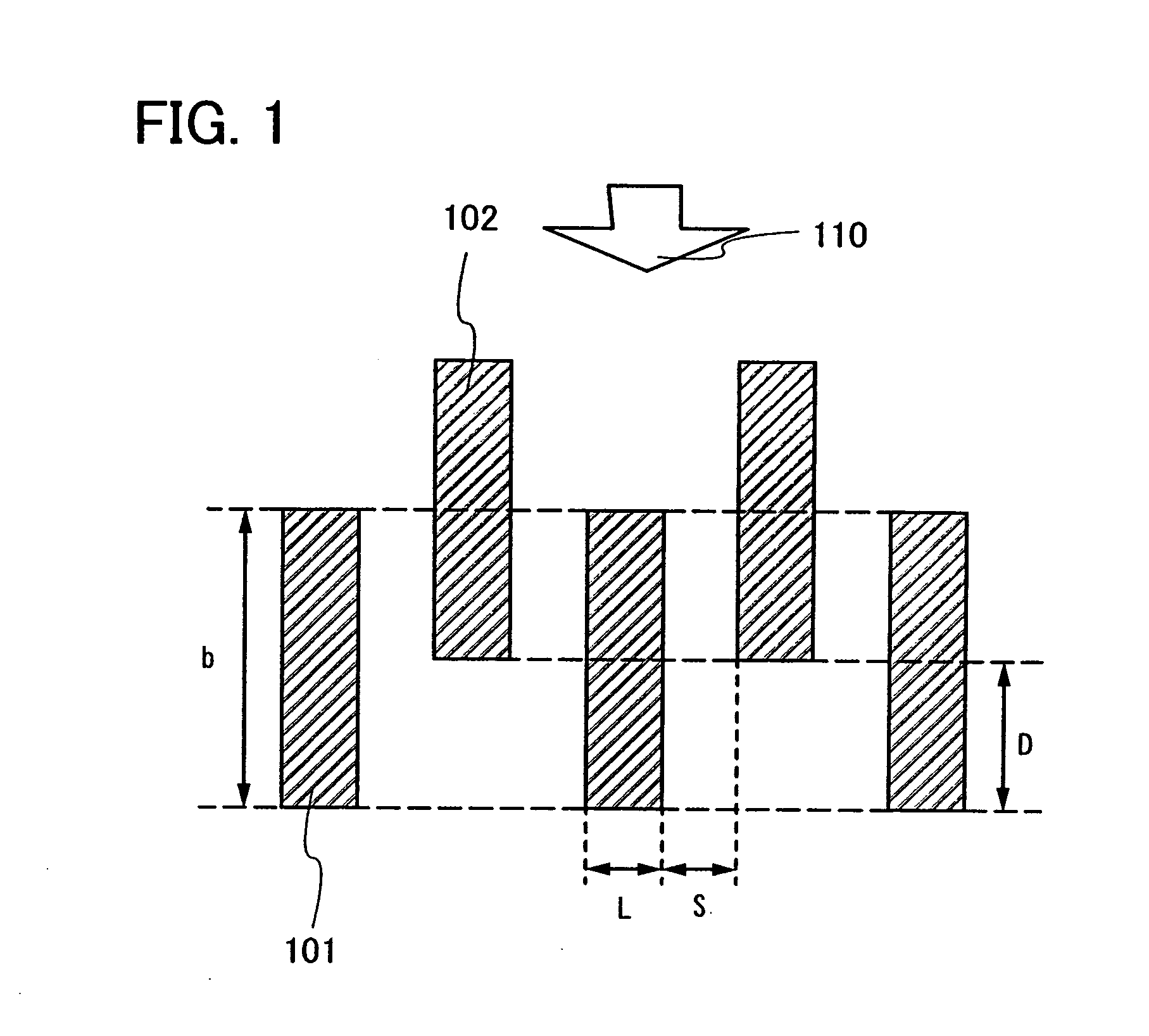
[0084]FIG. 7 illustrates another example of a polarizer having a wire grid structure of the present invention. In this embodiment mode, a polarizer in which grooves are formed on a light-transmitting substrate 701, a first group of metal wires 702 are provided on the grooves of the substrate, and a second group of metal wires 703 are provided on projections of the substrate. A method for manufacturing such a polarizer will be described below.

[0085]First, a light-transmitting substrate 701 is prepared. A light-transmitting material such as glass, ceramics, a resin or the like can be used for the light-transmitting substrate 701. Further, a high refractive index glass substrate of which refractive index is controlled by controlling impurities in glass can be used for the light-transmitting substrate 701.

[0086]Next, the light-transmitting substrate 701 is processed to form grooves with a width of (L+2S). As a method for processing the light-transmitting substrate 701, a laser etching m...


PUM

PropertyMeasurementUnit
thicknessaaaaaaaaaa
widthaaaaaaaaaa
thicknessaaaaaaaaaa

Abstract

A polarizer in which parallel transmittance TP is increased and crossed transmittance TC is provided. Instead of arranging a plurality of all metal wires on one plane, a plurality of metal wires is separately formed on at least two different parallel planes, and adjacent meal wires among the plurality of metal wires are staggered in the polarizer. The heights of a first group of metal wires formed on a first plane and a second group of metal wires formed on a second plane, from a surface of the light-transmitting substrate are different. Further, a metal wire of the second group is provided to be more distant from the light-transmitting substrate than the first group of metal wires by distance D, and the distance D is smaller than the thickness of the first group of metal wires.

Description

BACKGROUND OF THE INVENTION[0001]1. Field of the Invention[0002]The present invention relates to a polarizer and a semiconductor device including the polarizer. The present invention relates to, for example, an electronic device equipped with an electro-optic device typified by a liquid crystal display panel using a polarizer or a light-emitting display device including an organic light-emitting element using a polarizer, as a component.[0003]Note that in this specification, the term “semiconductor devices” refers to any type of devices in general, which can operate using semiconductor characteristics. Electro-optic devices, semiconductor circuits, and electronic devices are all included in the category of the semiconductor devices.[0004]2. Description of the Related Art[0005]Light of which electric vibration is biased to a certain direction is referred to as polarized light whereas light having random electric vibration is called natural light. The display principle of liquid cryst...

Claims


Application Information

Patent Timeline
Patent Type & Authority Applications(United States)
IPC IPC(8): G02B5/30B05D5/06
CPCG02B5/3058
Inventor NISHIDA, JIROKUBOTA, DAISUKE
Owner SEMICON ENERGY LAB CO LTD
Why Eureka
Try Eureka