Zoom Lens and image pickup apparatus

a pickup apparatus and zoom lens technology, applied in the field of new zoom lens and new image pickup apparatus, can solve the problems of difficult to and the tilting of the cam track for moving the first lens group too steep to ensure sufficient stop accuracy, etc., to achieve sufficient stop accuracy and reduce the height of the camera body.

Inactive Publication Date: 2009-01-08
SONY CORP
View PDF1 Cites 30 Cited by
  • Summary
  • Abstract
  • Description
  • Claims
  • Application Information

AI Technical Summary

Benefits of technology

[0008]However, there is an issue in the known negative-positive-positive 3-group zoom lens. That is, the entire lens length in the maximum wide angle state is large, making it difficult to reduce a height of the camera body. Further, the tilting of a cam track for moving the first lens group is too steep to ensure sufficient stop accuracy.

Problems solved by technology

However, there is an issue in the known negative-positive-positive 3-group zoom lens.
That is, the entire lens length in the maximum wide angle state is large, making it difficult to reduce a height of the camera body.
Further, the tilting of a cam track for moving the first lens group is too steep to ensure sufficient stop accuracy.

Method used


Image

  • Zoom Lens and image pickup apparatus
  • Zoom Lens and image pickup apparatus
  • Zoom Lens and image pickup apparatus

Examples


first embodiment

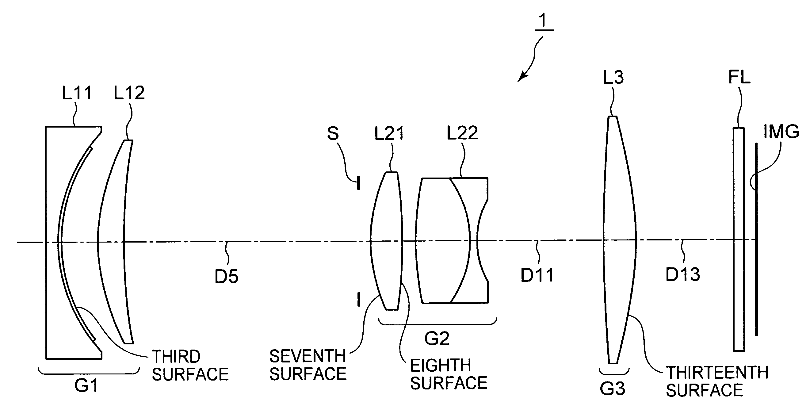
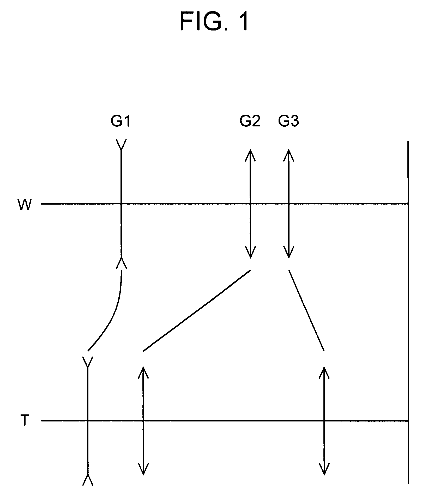
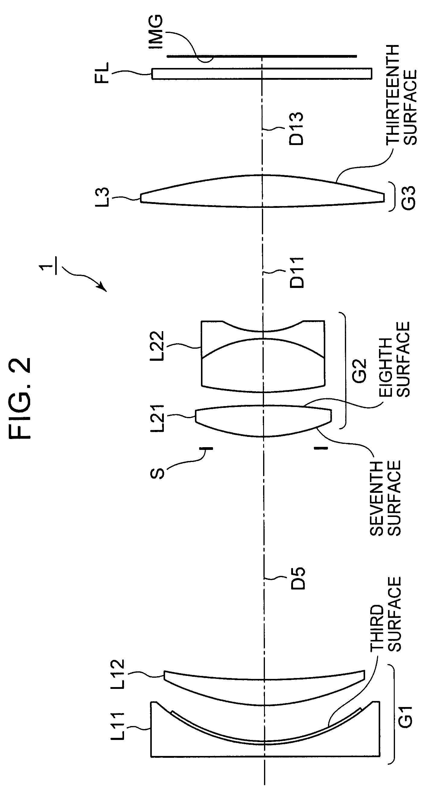
[0094]FIG. 2 shows the lens configuration of a zoom lens 1 according to the present invention. A first lens group G1 is configured by arranging, in order from an object side to the image side, a negative lens L11 whose concave surface is directed to the image side, and a positive lens L12 of meniscus shape whose convex surface is directed to the object side. A second lens group G2 is configured by arranging, in order from the object side to the image side, a positive lens L21 of biconvex shape and a cemented negative lens L22 composed of a positive lens of biconvex shape and a negative lens of biconcave shape. A third lens group G3 is composed of a positive lens L3 of biconvex shape. The negative lens L11 of the first lens group G1 is a compound lens in which a thin aspherical resin layer made of plastic is laminated on the image side lens surface. An aperture stop S is located adjacent to the object side of the second lens group G2. In zooming from the maximum wide angle state to t...

second embodiment

[0102]FIG. 6 shows the lens configuration of a zoom lens 2 according to the present invention. A first lens group G1 is configured by arranging, in order from an object side to an image side, a negative lens L11 whose concave surface is directed to the image side, and a positive lens L12 of meniscus shape whose convex surface is directed to the object side. A second lens group G2 is configured by arranging, in order from the object side to the image side, a positive lens L21 of biconvex shape, and a cemented negative lens L22 composed of a positive lens of biconvex shape and a negative lens of biconcave shape. A third lens group G3 is composed of a positive lens L3 of biconvex shape. An aperture stop S is located adjacent to the object side of the second lens group G2. In zooming from the maximum wide angle state to the maximum telephoto state, the aperture stop S is moved together with the second lens group G2. A filter FL is disposed between an image surface IMG and the third lens...

third embodiment

[0110]FIG. 10 shows the lens configuration of a zoom lens 3 according to the present invention. A first lens group G1 is configured by arranging, in order from an object side to an image side, a negative lens L11 whose concave surface is directed to the image side, and a positive lens L12 of meniscus shape whose convex surface is directed to the object side. A second lens group G2 is configured by arranging, in order from the object side to the image side, a positive lens L21 of biconvex shape, and a cemented negative lens L22 composed of a positive lens of biconvex shape and a negative lens of biconcave shape. A third lens group G3 is composed of a positive lens L3 of biconvex shape. An aperture stop S is located adjacent to the object side of the second lens group G2. In zooming from the maximum wide angle state to the maximum telephoto state, the aperture stop S is moved together with the second lens group G2. A filter FL is disposed between an image surface IMG and the third len...


PUM


Abstract

A zoom lens includes first to third lens groups having negative, positive, and positive refractive powers, respectively. When a lens position state changes from a wide-angle to a telephoto, all lens groups are moved in an optical axis direction so that a distance between the first and second lens groups decreases and a distance between the second and third lens groups increases. A close-distance focusing is accomplished by moving the third lens group. The first lens group is composed of negative and positive lens components. The second lens group is composed of a positive lens component, and a cemented lens composed of a positive lens of biconvex shape, and a negative lens of biconcave shape. The third lens group is composed of a positive lens component in which at least one of object-side and image-side lens surfaces is aspheric. The zoom lens is satisfied a predetermined condition.

Description

BACKGROUND OF THE INVENTION[0001]1. Field of the Invention[0002]The present invention relates to a new zoom lens and a new image pickup apparatus. In particular, the present invention relates to a small zoom lens and an image pickup apparatus using the zoom lens.[0003]2. Description of Related Art[0004]To record a subject image on cameras, a method for recording the subject image on an image pickup apparatus in which a photoelectric conversion element such as CCD (charge coupled device) or CMOS (complementary metal oxide semiconductor) is used has been known. In the method, the subject image formed on the image pickup apparatus is recorded by converting the intensity of the subject image to an electrical output using the respective photoelectric conversion elements.[0005]For example, a negative-positive-positive 3-group zoom lens is known as a suitable zoom lens for so-called digital video cameras and digital still cameras, which record a subject image by image pickup elements using...

Claims


Application Information

Patent Timeline
Patent Type & Authority Applications(United States)
IPC IPC(8): G02B15/14
CPCG02B15/177G02B15/143507
Inventor OHTAKE, MOTOYUKISUZUKI, ATSUSHI
Owner SONY CORP
Why Eureka
Try Eureka