Heat-dissipating casing structure

a casing and heat-dissipating technology, applied in the direction of lighting and heating apparatus, cooling/ventilation/heating modification, semiconductor devices, etc., can solve the problems of inability to replace the heat pipe of the heat-conductive block, difficult assembly process, etc., to achieve easy and rapid replacement, increase heat-dissipation efficiency, and increase the effect of heat-dissipation area

Active Publication Date: 2009-01-08
CHEMTRON RES
View PDF7 Cites 30 Cited by
  • Summary
  • Abstract
  • Description
  • Claims
  • Application Information

AI Technical Summary

Benefits of technology

[0007]The present invention provides a heat-dissipating casing structure. The structure includes a base seat and a casing. The casing can be slidably assembled on the base seat. When the casing is slidably assembled on the base seat, a heat-dissipating module is connected with the casing or the base seat at the same time via an installed portion that is disposed on the casing or the base seat. Hence, the heat from a heat-generating element on the base seat is transmitted to the casing. Therefore, the heat-dissipating module is assembled and can be replaced easily and rapidly. The casing further has a larger heat-dissipating area for increasing heat-dissipating efficiency.

Problems solved by technology

However, because the first side and the second side of the heat pipe are respectively welded or adhered to the heat-conductive block and the casing, the assembly process is difficult.
Moreover, the heat pipe of the heat-conductive block cannot be replaced.

Method used


Image

  • Heat-dissipating casing structure
  • Heat-dissipating casing structure
  • Heat-dissipating casing structure

Examples


first embodiment

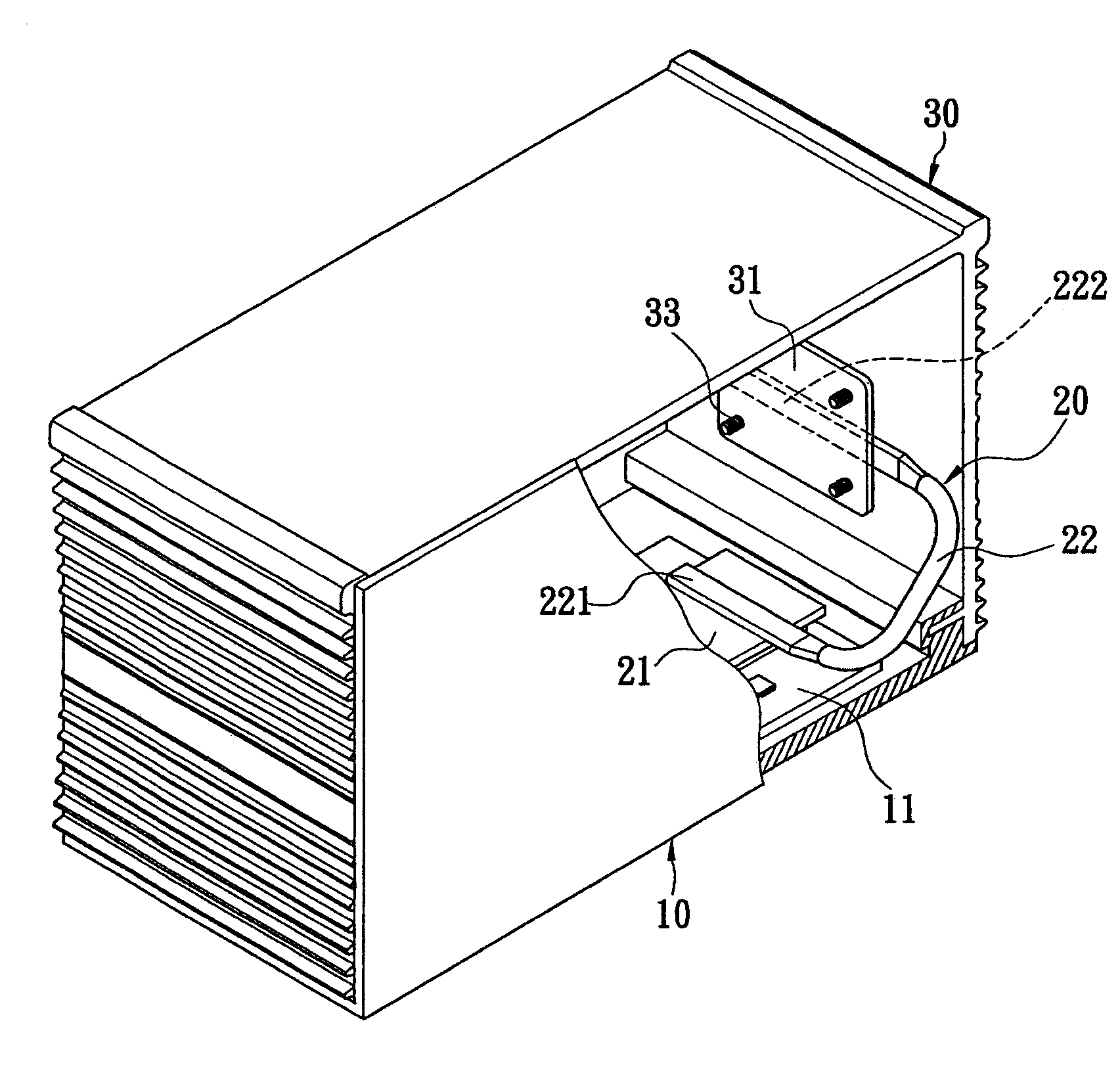
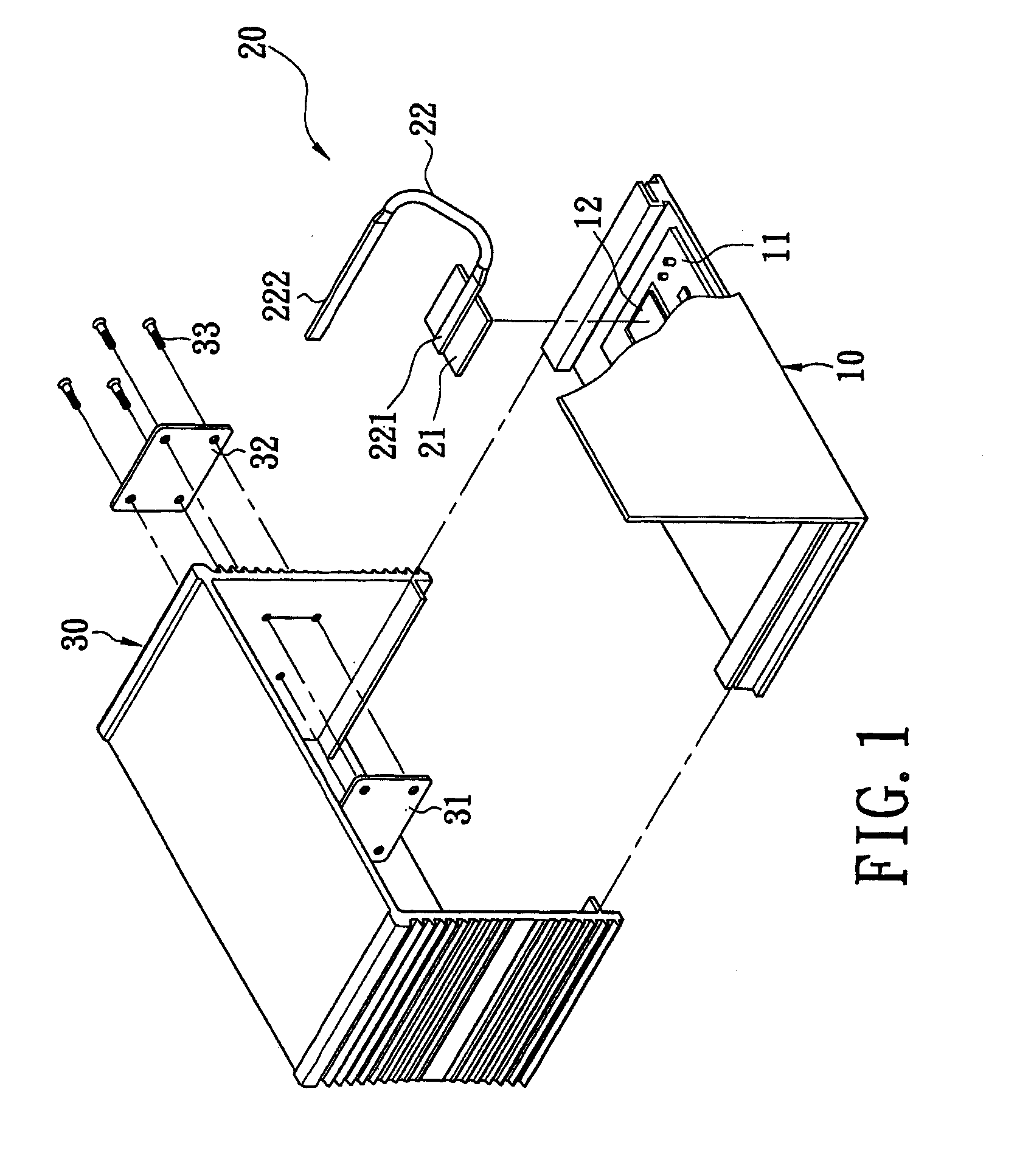
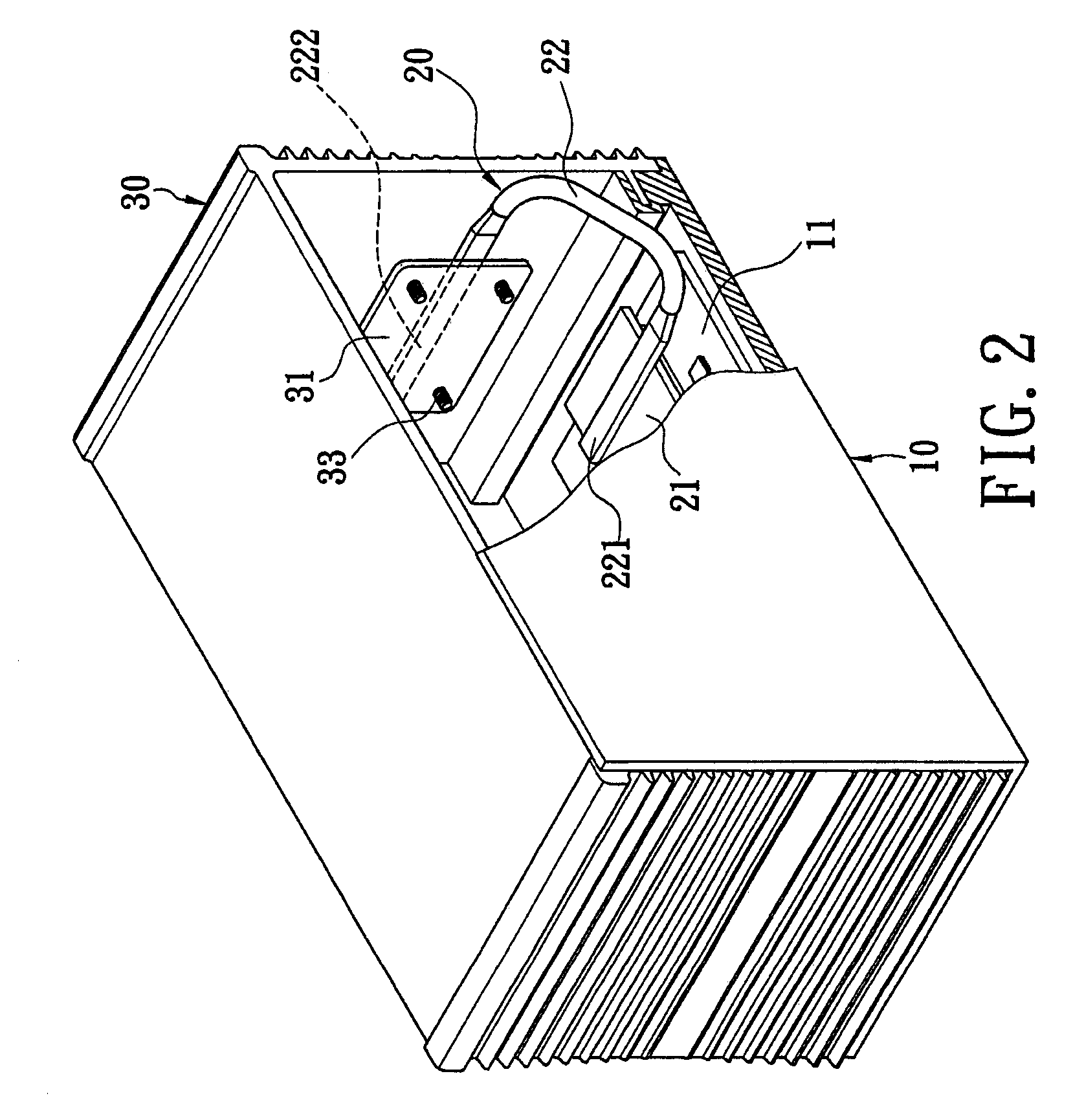
[0026]Referring to FIGS. 1 to 3, the present invention provides a heat-dissipating casing structure. The heat-dissipating casing structure comprises a base seat 10, a heat-dissipating module 20, and a casing 30. The base seat 10 has a PCB (Printed Circuit Board) 11 disposed thereon. The PCB 11 has a heat-generating element 12 such as CPU.

[0027]The heat-dissipating module 20 has a first heat-conducting block 21 and a first heat pipe 22. The heat-dissipating module 20 is screwed on the base seat 10 or is disposed on the base seat 10 by any fixing method. The first heat-conducting block 21 is made of heat-conducting metal material. The first heat-conducting block 21 is disposed on the heat-generating element 12 for absorbing heat from the heat-generating element 12.

[0028]In this embodiment, the first heat pipe 22 is bent in a U shape and has a first side 221 of a second side 222. The first side221 connects with the first heat-conducting block 21. The second side 222 is bent upward from...

fourth embodiment

[0038]FIGS. 8 to 10 show the present invention. A hard disk 40 is assembled on the base seat 10. A hard disk support 41 is covered on the hard disk 40. The PCB 11 is disposed on the hard disk support 41 and has a heat-generating element 12 (as shown in FIG. 9). The heat-dissipating casing structure further comprises a second heat pipe 14 that includes a first side 141 and a second side 142. The first side 141 connects to the hard disk support 41. The second side 142 extends from one end of the first side 141 to a lateral side of the base seat 10. The heat-dissipating module 20 has a first heat-conducting block 21 and a first heat pipe 22. The heat-dissipating module 20 is disposed on the base seat 10. The first heat-conducting block 21 has a vertical type heat sink 211 disposed thereon. The first heat-conducting block 21 is attached to the heat-generating element 12.

[0039]The first side 221 of the first heat pipe 22 connects with the first heat-conducting block 21. The second side 2...


PUM


Abstract

A heat-dissipating casing structure includes a base seat, a heat-dissipating module, and a casing. The heat-dissipating module is disposed on the base seat. The heat-dissipating module has a first heat-conducting block and a heat pipe, and one side of the heat pipe connects to the first heat-conducting block. The casing has an installed portion, and the casing is slidably assembled on the base seat for connecting the other side of the heat pipe with the casing via the installed portion. When the casing is slidably assembled on the base seat, the heat pipe is connected with the casing via the installed portion. Hence, the heat-dissipating module is assembled and replaced easily and rapidly. Moreover, the heat from a heat-generating element on the base seat is transmitted to the casing through the heat pipe for increasing heat-dissipating efficiency.

Description

BACKGROUND OF THE INVENTION[0001]1. Field of the Invention[0002]The present invention relates to a heat-dissipating casing structure, and particularly relates to a heat-dissipating casing structure for transmitting heat from a heat-generating element to a casing through a heat pipe in order to increase the heat-dissipating area.[0003]2. Description of the Related Art[0004]As the computer industry has developed the processing velocity of electronic devices (such as computers) has become faster and faster, subsequently the heat generated by the CPU has also increased. In order to dissipate the heat from the heat source to the external environment, a heat-dissipating device and a fan are usually used to help dissipate the heat.[0005]A known heat-dissipating module includes a heat pipe that has a first side and a second side. The first side of the heat pipe connects to a heat-conducting block that is disposed on a heat-generating element for absorbing heat from the heat-generating eleme...

Claims


Application Information

Patent Timeline
Patent Type & Authority Applications(United States)
IPC IPC(8): F28D15/00H05K7/20
CPCH01L23/4093H01L23/427H05K7/20536H01L2924/0002H01L2924/00
Inventor CHU, CHUNG-JUN
Owner CHEMTRON RES
Why Eureka
Try Eureka