
Method and an Apparatus for Separation and Injection of Water from a Water- and Hydrocarbon-Containing Outflow Down in a Production Well

a technology of production well and water well, which is applied in the direction of fluid removal, earth-moving drilling, borehole/well accessories, etc., can solve the problem that organic polymers are less resistant to high temperature and pressure conditions

Inactive Publication Date: 2009-01-15
SHORE TEC CONSULT
View PDF12 Cites 10 Cited by
  • Summary
  • Abstract
  • Description
  • Claims
  • Application Information

AI Technical Summary

Benefits of technology

[0068]When the injection pressure PI is provided in this manner, only water separation, and no water injection, is carried out. Such a pressure combination may, for example, be utilized for injection into an overpressured disposal formation, or for such injection at a fracture pressure. Through manipulation of said gas pressure P3 and thus the pressure P2 in the internal pressure manipulation region, the pressure manipulation region may be exposed to underpressure and overpressure, respectively, relative to the pressure P1 in the production flow. Alternation between water suction mode and water injection mode in the pressure manipulation region is thus possible.
[0111]As an alternative, the method, in step (F), may also be used to connect the second flow channel in a flow-communicating manner with at least one layer of the production formation, whereby the production formation also comprises said disposal formation. Preferably, such a disposal layer is underlying a hydrocarbon-containing layer of the production formation. Water-containing liquid injected into the disposal layer may thus contribute to provide pressure-support to the hydrocarbon-containing layer and thus contribute to increase the recovery therefrom.

Problems solved by technology

Organic polymers, however, are less resistant to high temperature- and pressure conditions typically prevailing in a well.

Method used


Image

  • Method and an Apparatus for Separation and Injection of Water from a Water- and Hydrocarbon-Containing Outflow Down in a Production Well
  • Method and an Apparatus for Separation and Injection of Water from a Water- and Hydrocarbon-Containing Outflow Down in a Production Well
  • Method and an Apparatus for Separation and Injection of Water from a Water- and Hydrocarbon-Containing Outflow Down in a Production Well

Examples


Embodiment Construction

OF EMBODIMENTS OF THE INVENTION

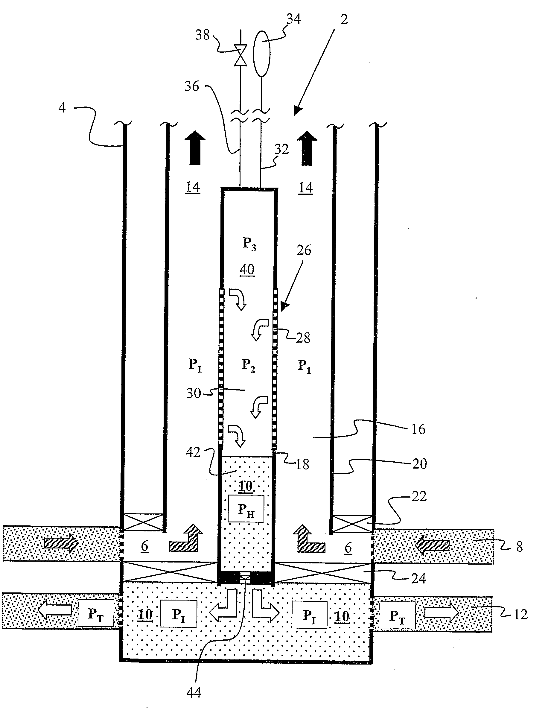
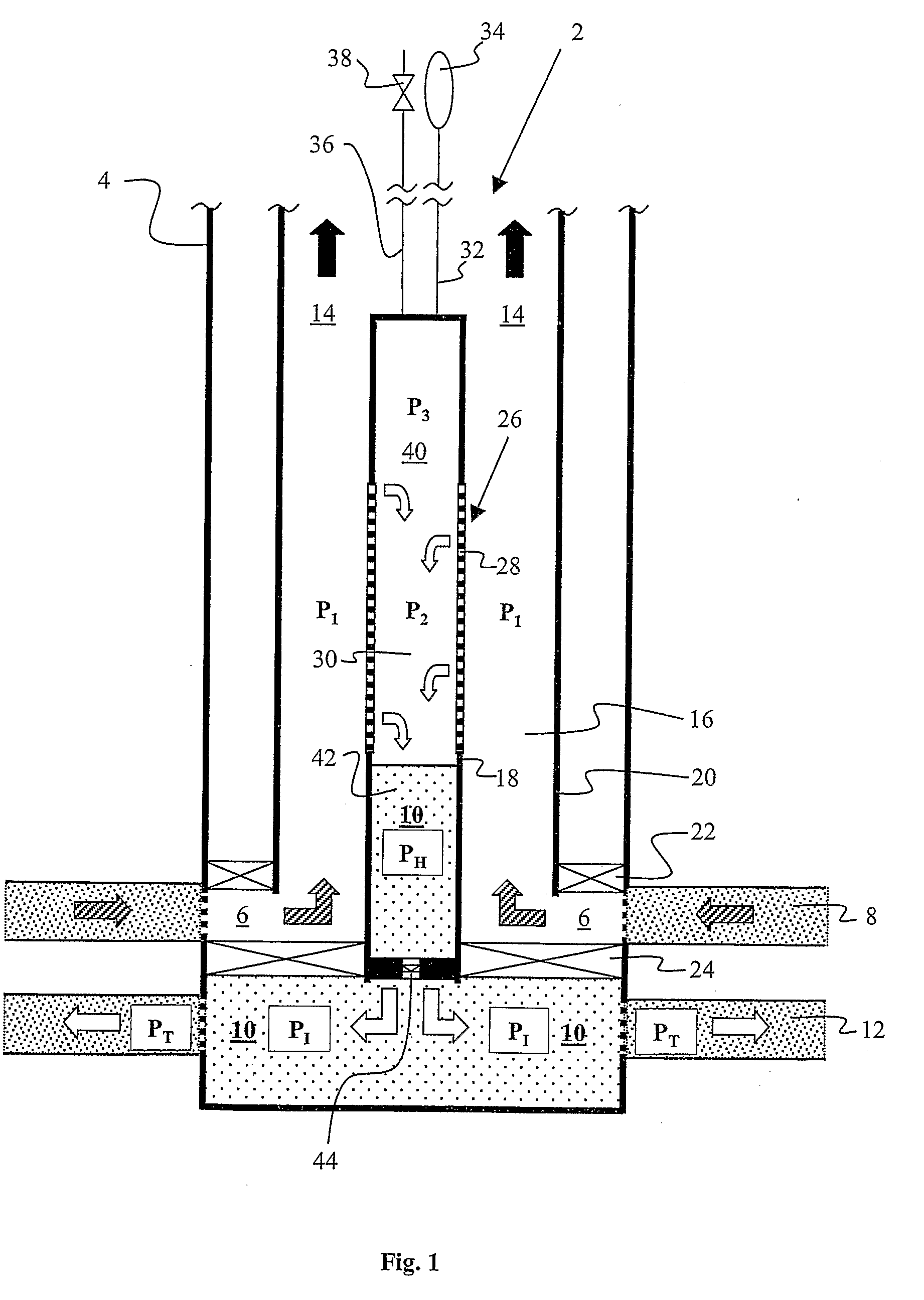
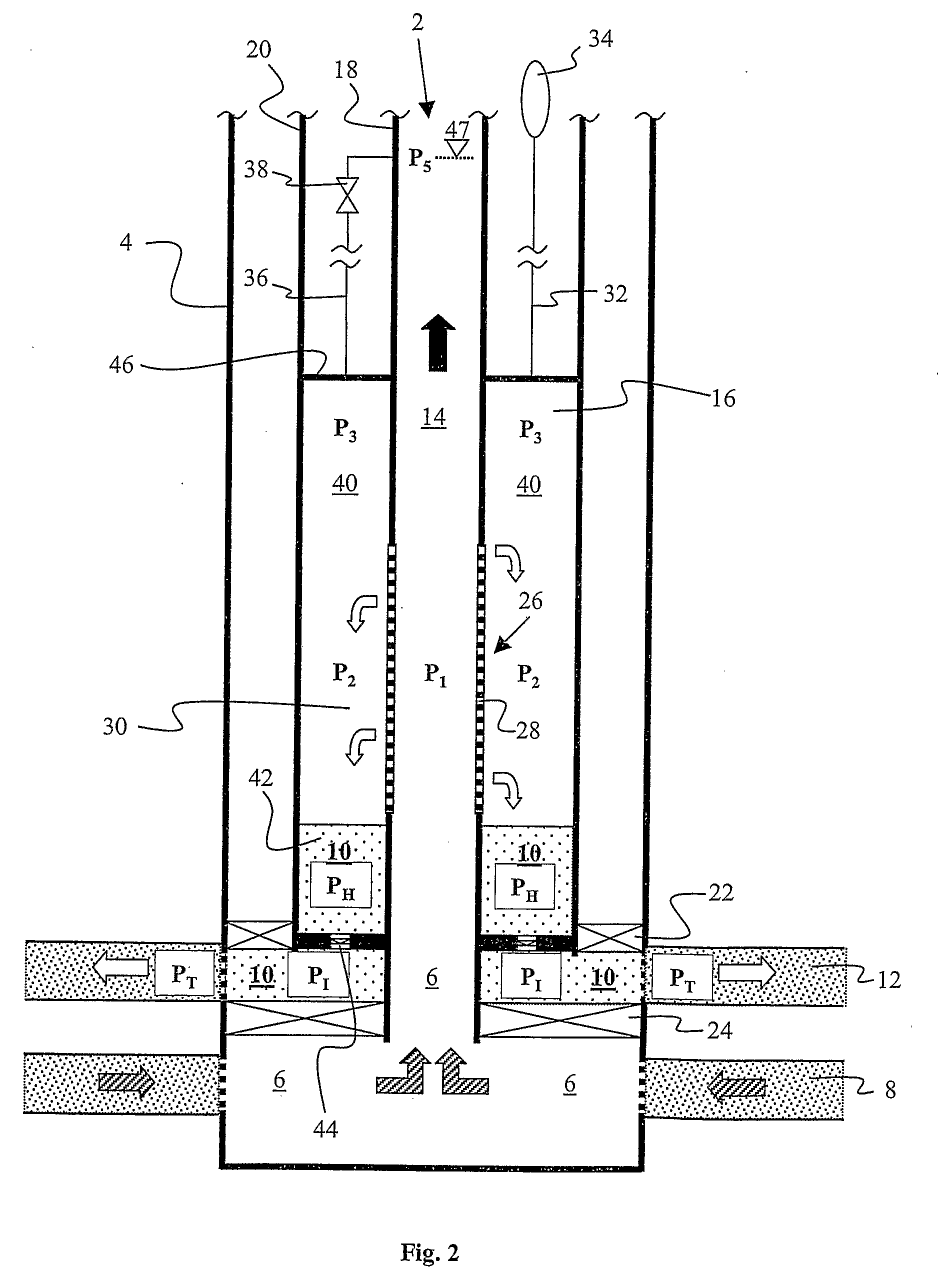
[0139]FIGS. 1-7 all show an apparatus 2 according to the invention. In a production well 4, the apparatus 2 is used to separate water from a water- and hydrocarbon-containing production flow 6 emanating from a production formation 8. The apparatus 2 is also used to inject a resulting water-containing permeate 10 into a disposal formation 12, whilst a resulting hydrocarbon-enhanced retentate 14 is produced to the surface. In the figures, the production flow 6; the flow of permeate 10; and the flow of retentate 14; are depicted with hachured arrows; white arrows; and black arrows, respectively. Among other things, the apparatus 2 comprises a first flow channel and a second flow channel, both of which are arranged within the production well 4.

[0140]The examples of embodiments shown in FIG. 1 and FIG. 2 show the simplest forms of the apparatus 2.

[0141]In the example of an embodiment according to FIG. 1, the first flow channel is comprised of an annulus (16...


PUM


Abstract

A method and apparatus of separating, in a production well, water from a water- and hydrocarbon-containing production flow emanating from at least one surrounding production formation; and also of injecting, in the production well, a resulting water-containing liquid into at least one surrounding disposal formation, whilst a resulting hydrocarbon-containing liquid is produced out of the production well. The water-containing liquid is separated from the production flow by using at least one water separation device being exposed to a pressure difference (P1-P2) that sucks water from the production flow and through the water separation device. Said water-containing liquid is thus provided. The water separation device may, for example, comprise at least one hydrophilic and water-permeable material. The pressure difference (P1-P2) may be provided through suitable adjustment of a gas pressure (P3) in a first gas column at a downstream side of the water separation device. The gas within the gas column may be supplied from a gas source at the surface, a gas source in a subsurface formation and / or gas being separated from the well flow.

Description

FIELD OF THE INVENTION [0001]This invention relates to hydrocarbon production from a subsurface reservoir via a production well. More particularly, the invention involves a method and an apparatus for separation and injection of water from a water- and hydrocarbon-containing production flow from the reservoir. By means of the invention, a water-containing liquid separated from the production flow may be injected directly into a subsurface disposal formation via the production well, and without initially having to bring the water-containing liquid up to the surface. Hydrocarbons remaining in the production flow after the water separation, i.e. a hydrocarbon-containing liquid, are produced out of the production well as a hydrocarbon-enhanced outflow.BACKGROUND OF THE INVENTION [0002]In addition to desirable hydrocarbons in the form of oil and / or gas, a hydrocarbon well oftentimes produces undesirable water. After having been produced for some time, such wells frequently produce large ...

Claims


Application Information

Patent Timeline
Patent Type & Authority Applications(United States)
IPC IPC(8): E21B43/38E21B43/00
CPCE21B43/385E21B43/40
Inventor WOIE, RUNEHEGRE, THOR MARTIN
Owner SHORE TEC CONSULT
Learn More