Water drinking device

a drinking water and water technology, applied in water/sewage multi-stage treatment, membranes, separation processes, etc., can solve the problems of complicated maintenance work, high likelihood of microbial contamination, and high likelihood of microbial proliferation, so as to reduce the frequency of maintenance work, keep drinking water even cleaner, and maintain clean

Inactive Publication Date: 2009-01-15
MITSUBISHI RAYON CLEANSUI CO LTD
View PDF3 Cites 16 Cited by
  • Summary
  • Abstract
  • Description
  • Claims
  • Application Information

AI Technical Summary

Benefits of technology

[0040]According to the drinking water device of the present invention, the drinking water flowing from the water outlet can be kept clean since microbes are removed due to the provision of the filtering device. In addition, it is possible to remove extremely tiny microbes when the filtering device is formed from a hollow fiber membrane, whereas the filtering device formed from an adsorbent is capable of removing malodor, and thus the drinking water can be kept even cleaner. Moreover, by providing the reserve passage, it is possible to keep the entire path of the drinking water in a clean condition without overloading the filtering device. Due to the filtering device and the reserve passage of the present invention, it is possible to reduce the frequency of the maintenance work, such as cleaning, and to suppress the running cost.
[0041]In addition, according to the drinking water device of the present invention, the replacement operation or the maintenance work of the filtering device will become easier by making the filtering device attachable / detachable.
[0042]Moreover, according to the drinking water device of the present invention, the maintenance work on the filtration filters can be carried out at an appropriate timing since the flow rate of the water flowing through the piping is detected, controlled, and indicated.

Problems solved by technology

Since such a conventional drinking water device 50 stores drinking water, which does not contain residual chlorine, in the bottle 53 or the water storage section 52, there are hygiene problems such as the high likelihood of microbial proliferation due to the sequential use, and the high likelihood of microbial contamination due to the necessity to incorporate air in the bottle 53 and the water storage section 52 when using the drinking water device 50.
However, since the sterilization device or the bacteria filtering device is provided inside the drinking water device and the paths therebetween are intricate, the complicated maintenance work is a problem.

Method used


Image

  • Water drinking device
  • Water drinking device
  • Water drinking device

Examples


first embodiment

[0101]One example of the first embodiment according to the present invention will be described below based on FIGS. 1 to 6.

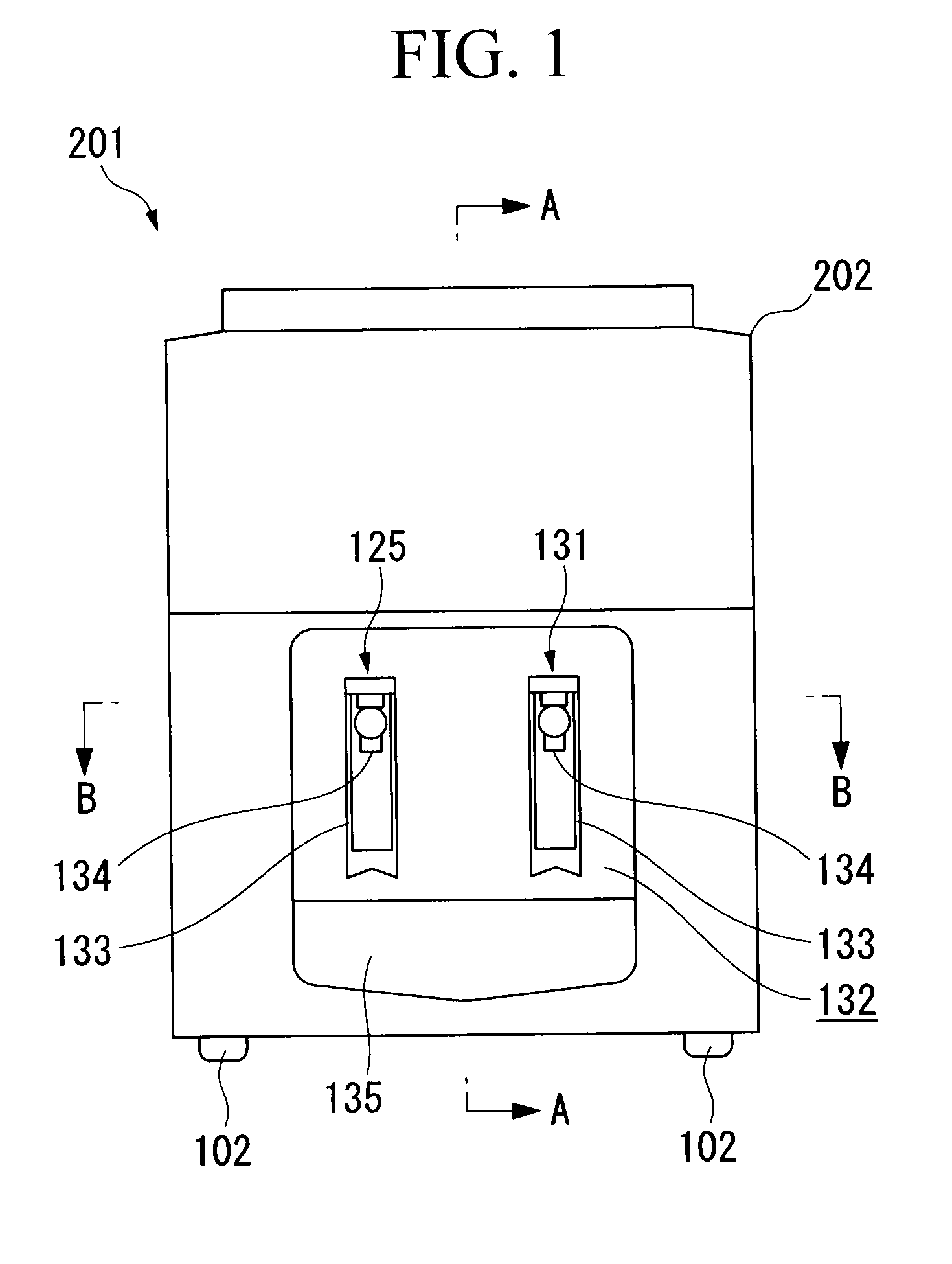
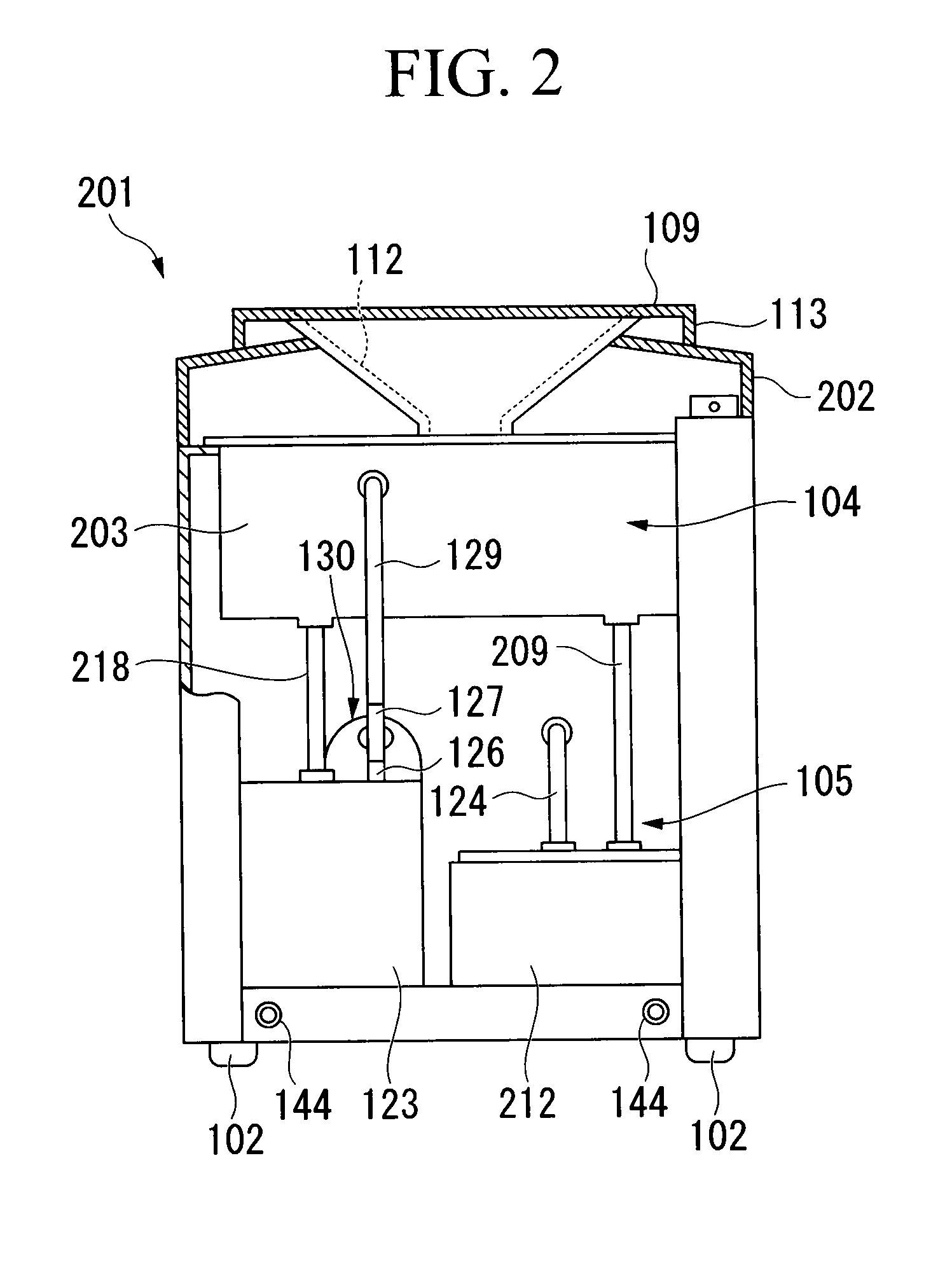
[0102]As shown in FIGS. 1 to 4, a drinking water device 201 has an installation type casing 202 of an almost square shape. The upper part of this casing 202 is mainly configured as a water storage chamber 104 whereas a lower part thereof is mainly configured as a device storage section 105. A cushion 102 made of rubber may be provided on four corners.

[0103]A water storage section 203 is provided in the water storage chamber 104 in the upper part of the casing 202. Above this water storage section 203, a bottle insertion slot 205 having a projecting portion 204 where a plurality of supply holes 210 are formed on the side wall thereof is provided, and a base 109 is further provided so that a bottle 206 (with a volume of, for example, about 20 L) for clean water as a drinking water tank can be installed to the drinking water device 201 by placing the opening 207 to...

second embodiment

[0145]Therefore, at the point in time where the drinking water ceased to flow out from the water outlet 134, the water flush pipe for cold water 128 is heated by the heater 141 and the inside of the water flush pipe for cold water 128 is sterilized, and thereafter the electromagnetic valve 142 is closed to seal the downstream side of the above-mentioned water flush pipe for cold water 128. Accordingly, it is possible to prevent microbes from entering from the water outlet 134 toward the filtration filter 130 side after sterilization. As a result, the downstream side of the filtration filter 130, that is, the water flush pipe for cold water 128 which is closer to the water outlet 134 side than the filtration filter 130 can be kept in a cleaner state, and the microbial contamination of the purified drinking water can be prevented. In this embodiment, although the electromagnetic valve 142 opens, and drinking water flows out from the water outlet 134 when the lever 133 is pressed, the...

third embodiment

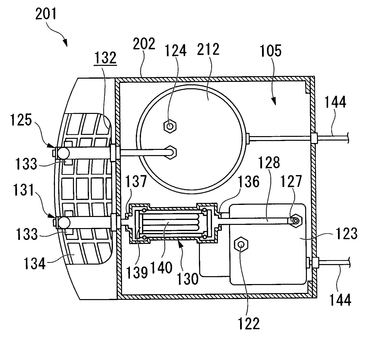
[0148]the present invention will be described based on FIGS. 9 to 21. Note that the descriptions for the reference symbols already explained earlier will be omitted.

[0149]As shown in FIGS. 9 and 10, an outlet port for hot water P1 and an outlet port for cold water P2 are each formed at the bottom 211 of the water storage section 203. A heating unit 212 is connected beyond the outlet port for hot water P1. The heating unit 212 is fixed to the bottom 213 of the casing 202 via a bracket or the like that is not illustrated and it is for heating (for example, up to about 80 to 90° C.) the drinking water supplied from the water storage section 203 via the water flow pipe for hot water 209 using an electrically heated wire or the like. The heating unit 212 is further connected to a water outlet of hot water 215a (refer to FIG. 10) via a water flow pipe for hot water 214. On the other hand, a filtration cartridge (filtering device) 217 is connected beyond the outlet port for cold water P2 a...


PUM

PropertyMeasurementUnit
angleaaaaaaaaaa
volumeaaaaaaaaaa
angleaaaaaaaaaa

Abstract

A drinking water device including a water storage section that stores drinking water inside an installation type casing; a water outlet that is connected to the water storage section via a passage and is located outside the casing; filtering device that is provided in the passage on further upstream side of the water outlet so as to be freely attachable/detachable; and a flow rate switch, which is provided between the water storage section and the water outlet and which is capable of detecting flow rate of the drinking water and also capable of outputting an actuating signal upon detecting the flow rate within a preset flow rate range.

Description

TECHNICAL FIELD[0001]The present invention relates to a drinking water device.BACKGROUND ART[0002]An installation type drinking water device has been known to date and this type of drinking water device has been used in households, offices, boardrooms, restrooms, and the like. A tank or a bottle containing a relatively large amount of drinking water is installed in a drinking water device so that the opening thereof is situated below to supply drinking water to the device. For example, as shown in FIG. 32, a drinking water device 50 is configured so that drinking water is supplied from a bottle 53 or the like to a water storage section 52 provided in a casing 51, and the drinking water stored in the water storage section 52 is heated or cooled to a desired temperature using a heating unit 55 or a cooling unit 56, and thereafter the water can be poured into a container such as a cup from a hot water outlet 57 or a cold water outlet 58 (refer to Patent Document 1).[0003]Since such a c...

Claims


Application Information

Patent Timeline
Patent Type & Authority Applications(United States)
IPC IPC(8): B01D35/14C02F1/00C02F103/04
CPCB01D61/18B01D63/024B01D2311/2626C02F1/001C02F1/281B01D2313/40C02F1/32C02F1/42C02F1/444C02F1/78C02F9/005C02F1/283C02F9/20C02F1/44C02F1/28
Inventor TAKEDA, HATSUMIHATAKEYAMA, ATSUSHIHORIUCHI, FUTOMITSUSAKAKIBARA, HIROKI
Owner MITSUBISHI RAYON CLEANSUI CO LTD
Why Eureka
Try Eureka