Directional Neutron Detector

a neutron detector and directional technology, applied in the field of directional neutron detectors, can solve the problems of low neutron detection efficiency, inability to minimize the sensitivity of gamma radiation, and x-ray separation, so as to reduce gamma detection efficiency, and minimize cross-talk with adjacent fibers

Inactive Publication Date: 2009-01-15
SUHAMI AVRAHAM
View PDF11 Cites 87 Cited by
  • Summary
  • Abstract
  • Description
  • Claims
  • Application Information

AI Technical Summary

Benefits of technology

[0106]The detector may also detect thermal and epithermal neutrons if the plastic scintillator fibers are loaded with B10 or Li6. Loading with Li6 is the preferred implementation as it creates higher energy secondary particles that are easier to differentiate from electrons created by Gamma rays.
[0113]An important feature of the fiber arrays is the filling of the space between the fibers by several micron sized aerogels. This structure equivalent to “air” cladding of the plastic core, enables a large proportion of the scintillation photons to stay and propagate within the fiber and minimize the cross-talk with adjacent fibers.
[0114]To increase the neutron detection efficiency while decreasing gamma detection efficiency it is useful to surround the neutron detector with a lead (Pb) lining. While the lead lining will absorb some of the gamma / x rays, it will also amplify the neutron flux due to the (n,2n) reactions in lead, specially due to the [Pb206+n→Pb206+2n] reaction, as Pb constitutes 24% of natural lead.

Problems solved by technology

Thus the main challenge of neutron detection is the elimination or differentiation from Gamma and X-rays.
Notwithstanding the technological problems associated with the specific semiconductors, such p-n diodes are inherently small; consequently they have low efficiencies to detect neutrons.
However such thick fibers cannot minimize the sensitivity to Gamma radiation and the detector built with such thick fibers cannot be inherently directional, without imaging the track of the recoil proton.

Method used


Image

  • Directional Neutron Detector
  • Directional Neutron Detector
  • Directional Neutron Detector

Examples


Embodiment Construction

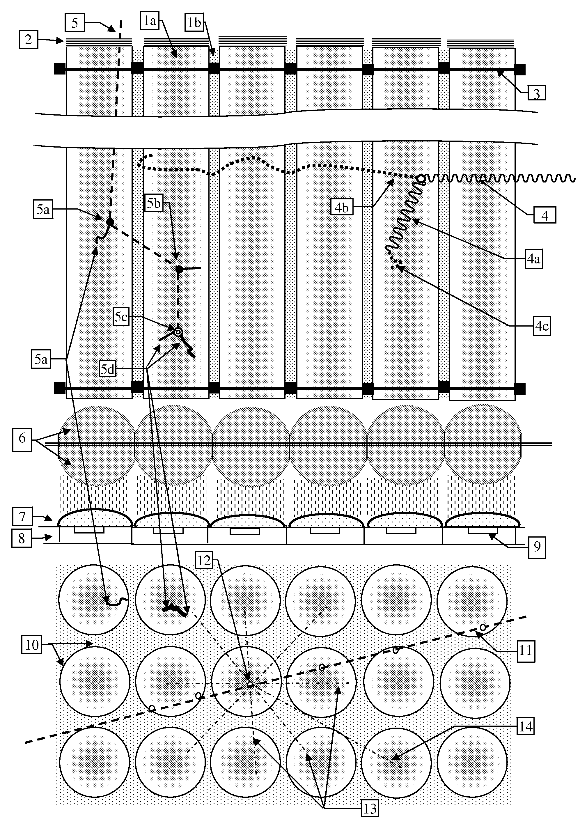
[0134]FIG. 1 illustrates a fast and thermal Neutron detector consisting of an array of straight plastic scintillations fibers 1a, loaded with a material that has a high thermal neutron cross section, coupled optically to a photodetector array 8. The beam of photons exiting the fibers are first collimated by two arrays 6 of semi-ball lenses placed back-to-back so that their combined effect is like full ball-lenses. The collimated beams are then focused onto the active areas 9 of each photodetector pixel by a lenslet array 7 attached or deposited on the photodetector array 8, such as a CMOS or CCD active pixel array. One end of the fiber is coated with a dielectric or metallic mirror 2 that reflects the scintillation photons back to the other end. The width of the scintillation fibers is determined by the range of the protons scattered by the neutrons and the range of the heavy particles, tritons and alphas created by the specific thermal neutron capture reaction of the material loade...


PUM

PropertyMeasurementUnit
diameteraaaaaaaaaa
refractive indexaaaaaaaaaa
reflectivityaaaaaaaaaa

Abstract

A directional neutron detector consisting of very thin plastic scintillation fibers and optically coupled to a photo-sensor array, where the directionality of Neutrons is estimated from the sequence of fibers traversed by the scattered protons and energy deposited in each one of them . Several fabrication methods of the large thin fiber arrays are described.

Description

[0001]This application claims the benefit of the filing of U.S. Provisional Patent application US60 / 928,272 filed on May 09, 2007 titled Neutron Detectors and US Provisional Patent application US61 / 065623 filed on Feb. 14, 2008 titled Neutron-Gamma Detectors incorporated herein in their entirety by reference.RELEVANT PATENTS PATENT APPLICATIONS AND PUBLICATIONS[0002]The patents and patent applications below are incorporated in this application by reference.[0003]U.S. Pat. No. 7,335,891 Gamma and neutron radiation detector by Kniss, et al.[0004]U.S. Pat. No. 7,304,309 “Radiation Detector” by Avraham Suhami[0005]U.S. Pat. No. 7,145,149 Flexible composite radiation detector by Cooke, et al.[0006]U.S. Pat. No. 7,141,799 Fiber optic thermal / fast neutron and Gamma ray scintillation detector, Neal et al.[0007]U.S. Pat. No. 7,126,148 Neutron detection based on boron activated liquid scintillation by Murray, et al.[0008]U.S. Pat. No. 7,057,187 Scintillator optical system and method of manufa...

Claims


Application Information

Patent Timeline
Patent Type & Authority Applications(United States)
IPC IPC(8): G01T3/06B29C35/12B28B17/00
CPCG01T3/06
Inventor SUHAMI, AVRAHAM
Owner SUHAMI AVRAHAM
Why Eureka
Try Eureka