Ink jet recording head

a recording head and jet technology, applied in the field of jet recording head, can solve the problems of increasing the ejection amount of ink, the influence of an increase in the viscosity of ink, and the instability of the bubble generation state, so as to achieve stable ejection amount, reduce image quality, and reduce the characteristic of ejection

Inactive Publication Date: 2009-01-15
CANON KK
View PDF3 Cites 14 Cited by
  • Summary
  • Abstract
  • Description
  • Claims
  • Application Information

AI Technical Summary

Benefits of technology

[0016]A principal object of the present invention is to provide an ink jet recording head with a plurality of ejection amounts capable of suppressing a lowering in ejection characteristic of first ejection and a lowering in image quality due to a change in color density or color tone, thus being capable of stably realizing ejection amounts from various ejection outlets for ejecting ink with different ejection amounts.

Problems solved by technology

On the other hand, in the case where the head temperature of the ink jet recording head is increased due to an increase in ambient temperature or continuous use of the ink jet recording head, the ink ejection amount can be increased or a bubble generation state can be unstable.
When the ejection outlet diameter is small, ink from the neighborhood of ejection outlet is liable to be affected by the influence of an increase in viscosity of the ink due to vaporization of water content from the ejection outlet.
Further, by a change in change of the ink, a color density or a color tone of an image to be recorded on a recording medium (material) is changed, so that a lowering in image quality such as an occurrence of streak, non-uniformity, or the like can occur.
However, such a conventional ink jet recording head is accompanied with the following problem.
That is, when the recording element substrate is heated correspondingly to a relatively small ejection amount, an ejection amount of a portion with a relatively large ejection amount is excessively large, so that ejection of the ink is unstable.
However, in that case, a lowering in recording speed and an increase in production cost due to complicated pulse control and a lowering in recording speed due to an increased time required for increasing a head temperature of the ink jet recording head are caused to occur.
In the case where a warming heat generating resistor is provided in the same plane as an ejection heat generating resistor in a conventional ink jet recording head, it is necessary to dispose wiring for driving each of resistors, so that a recording element substrate is increased in size, thus resulting in an increase in production cost.

Method used


Image

  • Ink jet recording head
  • Ink jet recording head
  • Ink jet recording head

Examples


first embodiment

[0053]The description will be made about a basic structure of an ink jet recording head cartridge according to an embodiment of the present invention.

[0054]In an ink jet recording head of the present embodiment, a recording head portion is an ink jet recording head of the type wherein a recording operation is formed by using an electrothermal transducer element for generating a thermal energy by creating a film boiling in the ink in response to an electric signal.

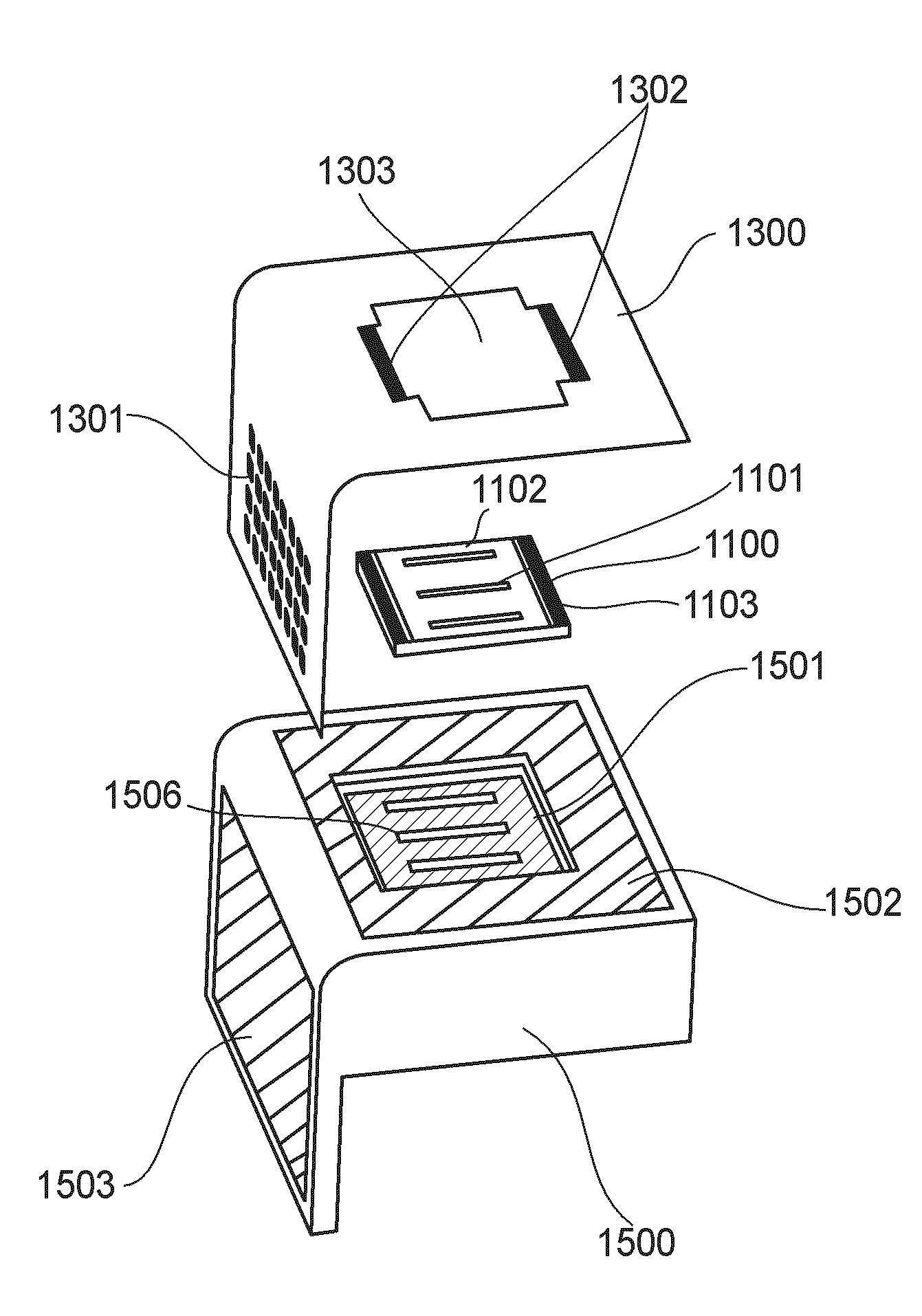
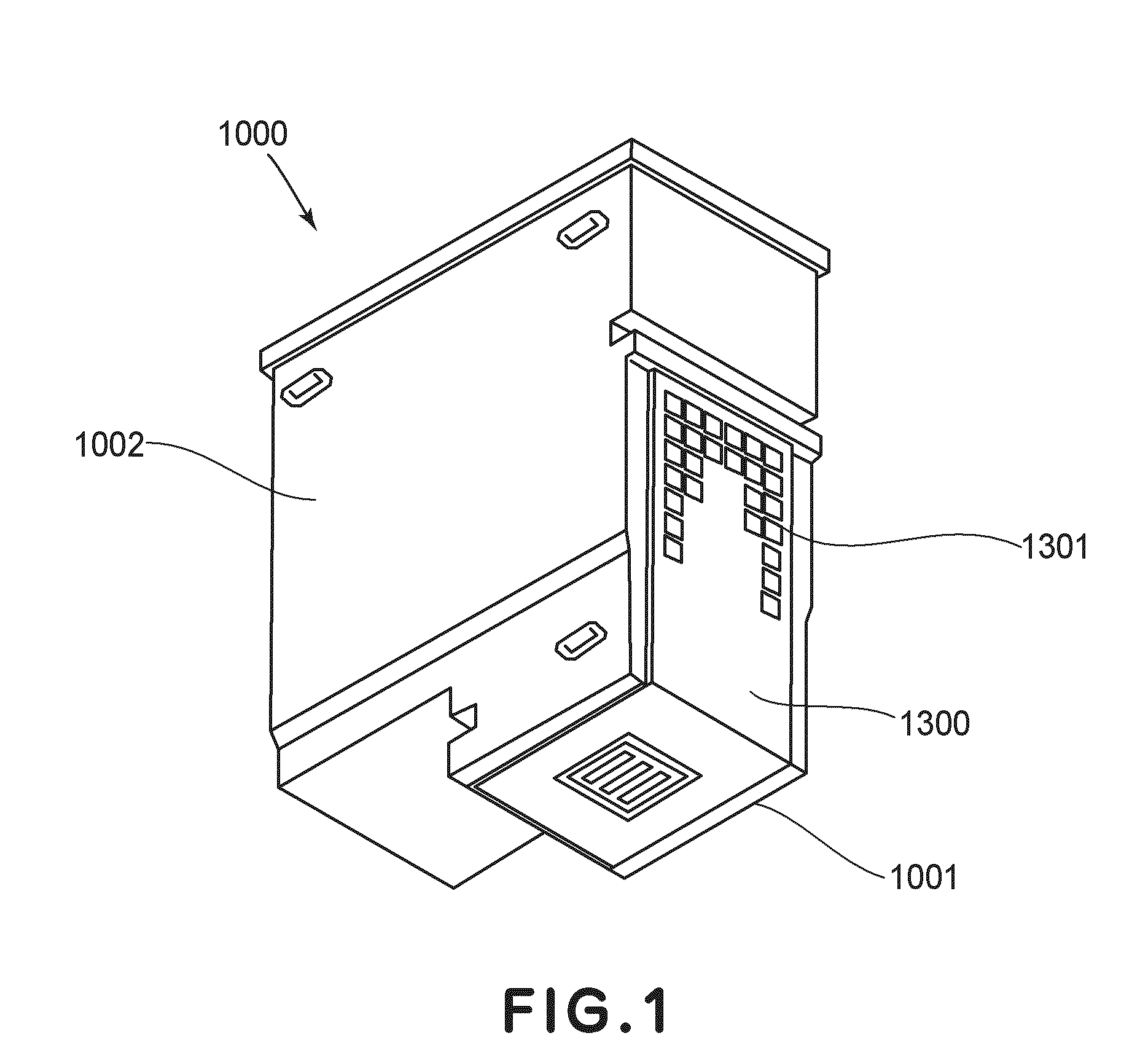
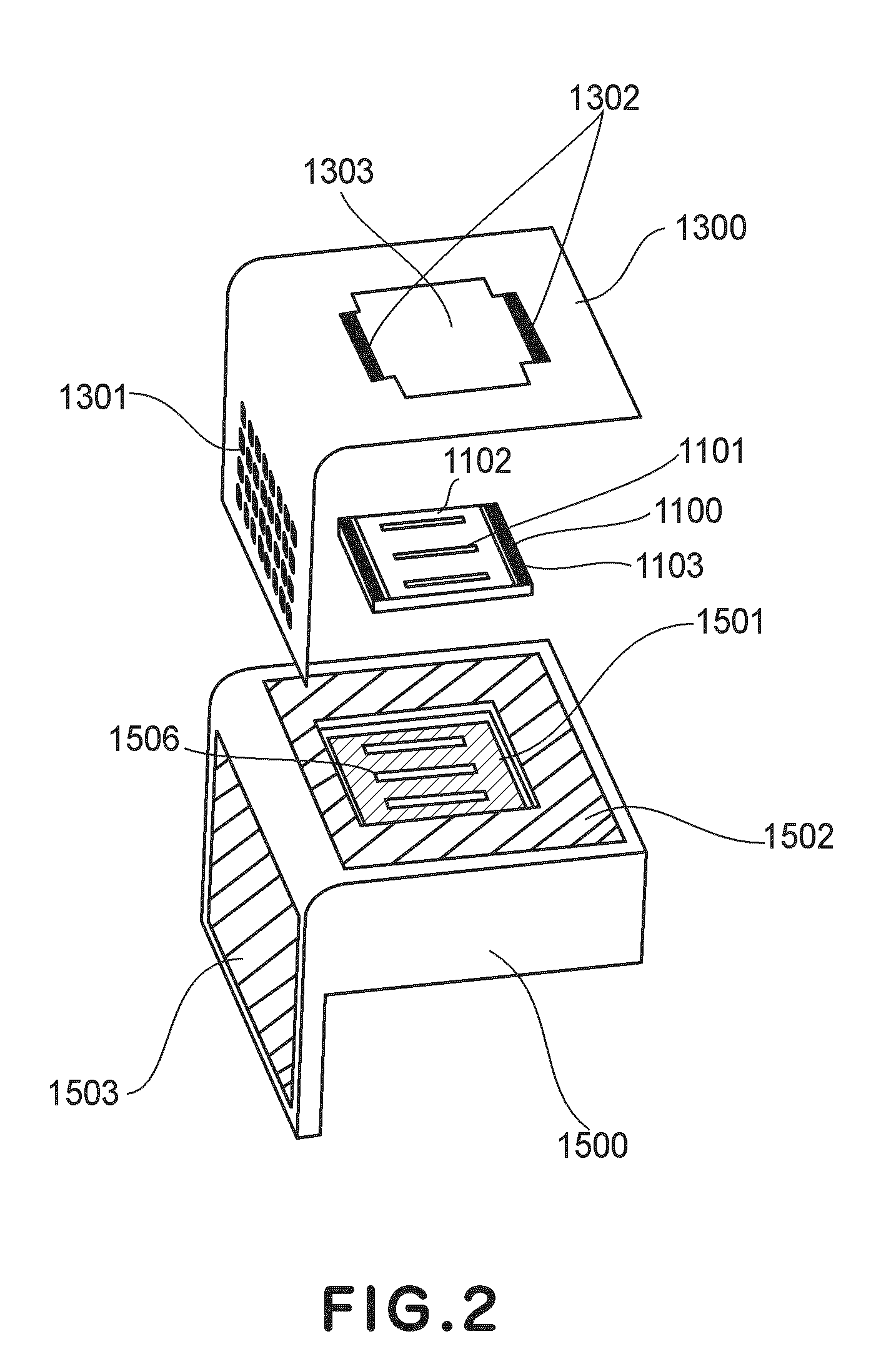
[0055]FIG. 1 is a perspective view of a recording head cartridge according to the embodiment of the present invention, wherein a recording head portion 1001 has a recording element substrate 1100 for ejecting an ink droplet by the action of the film boiling by heating the ink by an electrothermal transducer element which has a heat generating resistor. It comprises an electrical wiring substrate 1300 for applying the driving signal from a main assembly of a recording apparatus to the recording element substrate 1100, and a ...

second embodiment

[0089]FIG. 11 is a schematic plan view showing a recording element substrate 1100 in this embodiment. Referring to FIG. 11, ejection outlet arrays 11, 12 and 13 are used for ejecting cyan ink, ejection outlet arrays 21, 22 and 23 are used for ejecting magenta ink, and ejection outlet arrays, 31, 32 and 33 are used for ejecting yellow ink. In the case of the same color ink, a common ink supply port 10 is used. In correspondence with each of the ejection outlet arrays, first ejection heat generating resistor arrays 311, 321 and 331, second ejection heat generating resistor arrays 312, 322 and 332, and third ejection heat generating resistor arrays 313, 323 and 333 are provided. Further, first warming heat generating resistors 511, 521 and 531 for ejection of ink in a large amount, second warming heat generating resistors 512, 522 and 532 for ejection of ink in a small amount, and third warming heat generating resistors 513, 523 and 533 for ejection of ink in a very small amount are fo...

third embodiment

[0103]FIGS. 12 and 13 are enlarged values of A portion shown in FIG. 7, for illustrating positions of the first warming heat generating resistors. FIG. 13 is taken along a-a line shown in FIG. 12. As shown in FIGS. 12 and 13, a part of a warming heat generating resistor 500 is disposed on a bottom surface of an ink flow path 1104 communicating with an ejection outlet 1101. Further, the warming heat generating resistor 500 is laminated above a recording element substrate 1100 via an ejection heat generating resistor 219 and an insulating layer 216 so that it extends above and over the ejection heat generating resistor 219 and surrounds an our periphery of the ejection heat generating resistor 219 when it is projected onto the ejection heat generating resistor 219 in a lamination direction. In this manner, a first warming heat generating resistor 511 is provided correspondingly to a first ejection heat generating resistor array for ejection in a large ejection amount. The warming heat...


PUM


Abstract

An ink jet recording head includes ejection resistors for generating thermal energy for ejecting ink; warming resistors for generating thermal energy for heating the ink; ejection outlets, provided correspondingly to the ejection resistors, for ejecting the ink; and a recording element substrate provided with ink flow paths provided correspondingly to and for supplying the ink to the ejection outlets, the ejection resistors, the warming resistors, a first ejection outlet array portion including the ejection outlets, and a second ejection outlet array portion including the ejection outlets. An amount of one ink droplet to be ejected from an ejection outlet of the first ejection outlet array portion is different from that from an ejection outlet of the second ejection outlet array portion. The warming resistors are formed above the recording element substrate through the ejection resistors and an insulating layer with respect to a lamination direction of the recording element substrate and are disposed between the ejection resistors and the ink flow paths. The warming resistors include a first warming resistor disposed at the first ejection outlet array portion with a larger ejection amount and a second warming heat generating resistor disposed at the second ejection outlet array portion with a smaller ejection amount.

Description

FIELD OF THE INVENTION AND RELATED ART[0001]The present invention relates to an ink jet recording head in which a traveling droplet is produced by ejection of ink to effect recording. Particularly, the present invention relates to the ink jet recording head in which an ejection heat generating resistor for ejecting the ink in a state in which the ink is heated by a warming heat generating resistor is driven.[0002]An ink jet recording head of a thermal type effects recording by applying driving energy to an ejection heat generating resistor to cause film boiling of ink, so that an ink droplet is ejected from an ejection outlet by energy generated by the film boiling. Generally, ink used in the ink jet recording head is lowered in viscosity with an increasing ink temperature. For that reason, even in the case where a certain amount of driving energy is applied to the ejection heat generating resistor, a bubble generation state of the ink varies depending on a head temperature of the i...

Claims


Application Information

Patent Timeline
Patent Type & Authority Applications(United States)
IPC IPC(8): B41J2/05
CPCB41J2/04528B41J2/04553B41J2/04563B41J2/0458B41J2002/14475B41J2/14056B41J2/14072B41J2/14129B41J2002/14362B41J2/1404
Inventor FUKUI, SHIGEKIIKEGAME, KEN
Owner CANON KK
Why Eureka
Try Eureka