Unlock instant, AI-driven research and patent intelligence for your innovation.
Radio-Controlled Timepiece and Control Method for a Radio-Controlled Timepiece
Active Publication Date: 2009-01-15
SEIKO EPSON CORP
View PDF8 Cites 32 Cited by
Summary
Abstract
Description
Claims
Application Information
AI Technical Summary
This helps you quickly interpret patents by identifying the three key elements:
Problems solved by technology
Method used
Benefits of technology
Benefits of technology
[0011]The radio-controlled timepiece and the control method for a radio-controlled timepiece according to the present invention reduce the effect of the reception environment and reduce power consumption when acquiring time information.
Problems solved by technology
While the radio-controlled timepiece has an AGC circuit, the threshold values used by the A / D conversion circuit for digitizing the signal are fixed, and the reception environment may therefore prevent acquiring the correct time code.
This unit that a relatively long time is required to determine that the correct time information cannot be acquired if the reception environment is poor, and power consumption increases accordingly
Method used
Image
Click on the blue label to locate the original text in one second.
Reading with bidirectional positioning of images and text.
Examples
embodiment 1
[0075]A radio-controlled timepiece 1 according to a first preferred embodiment of the invention is described next with reference to the accompanying figures.
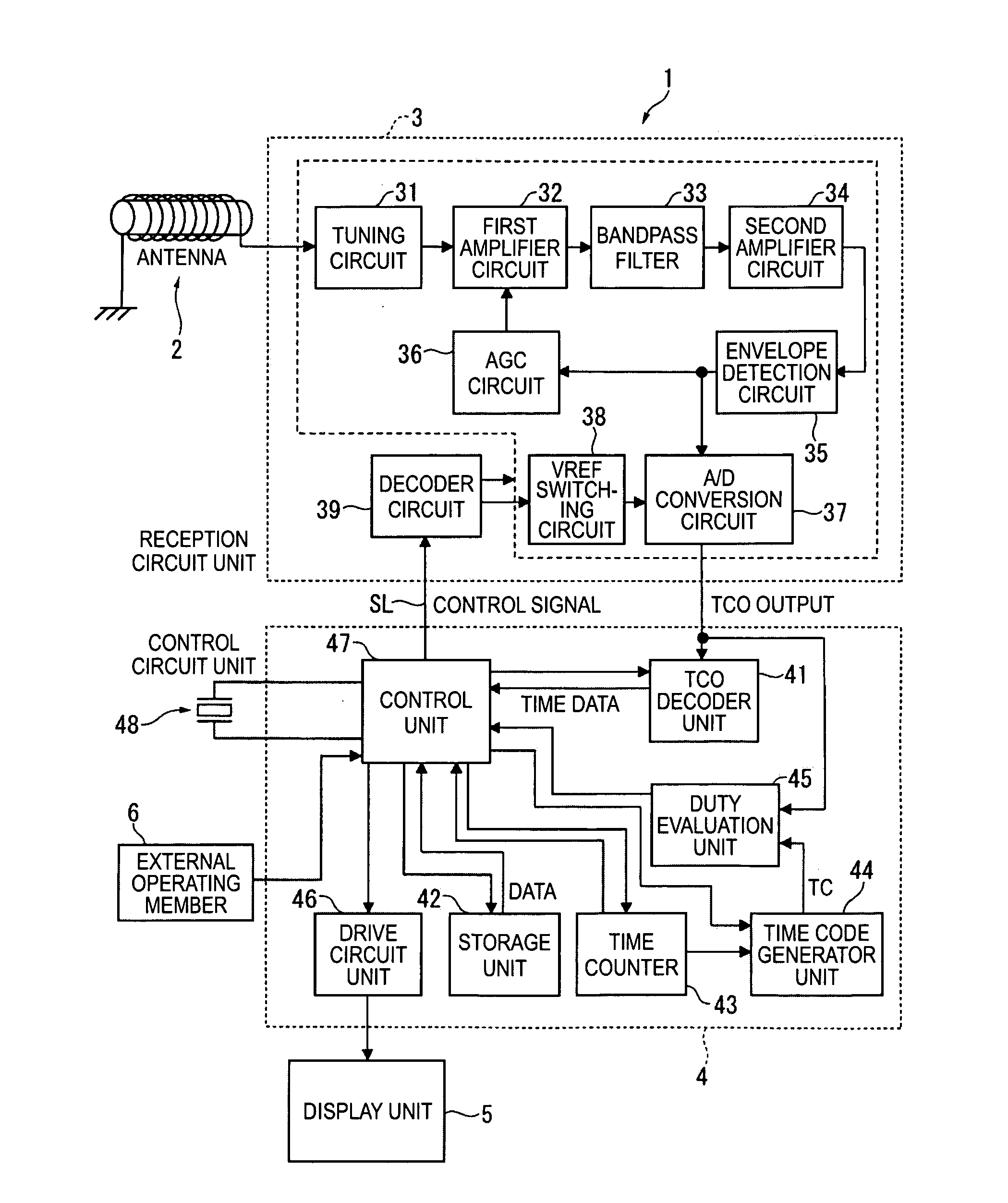
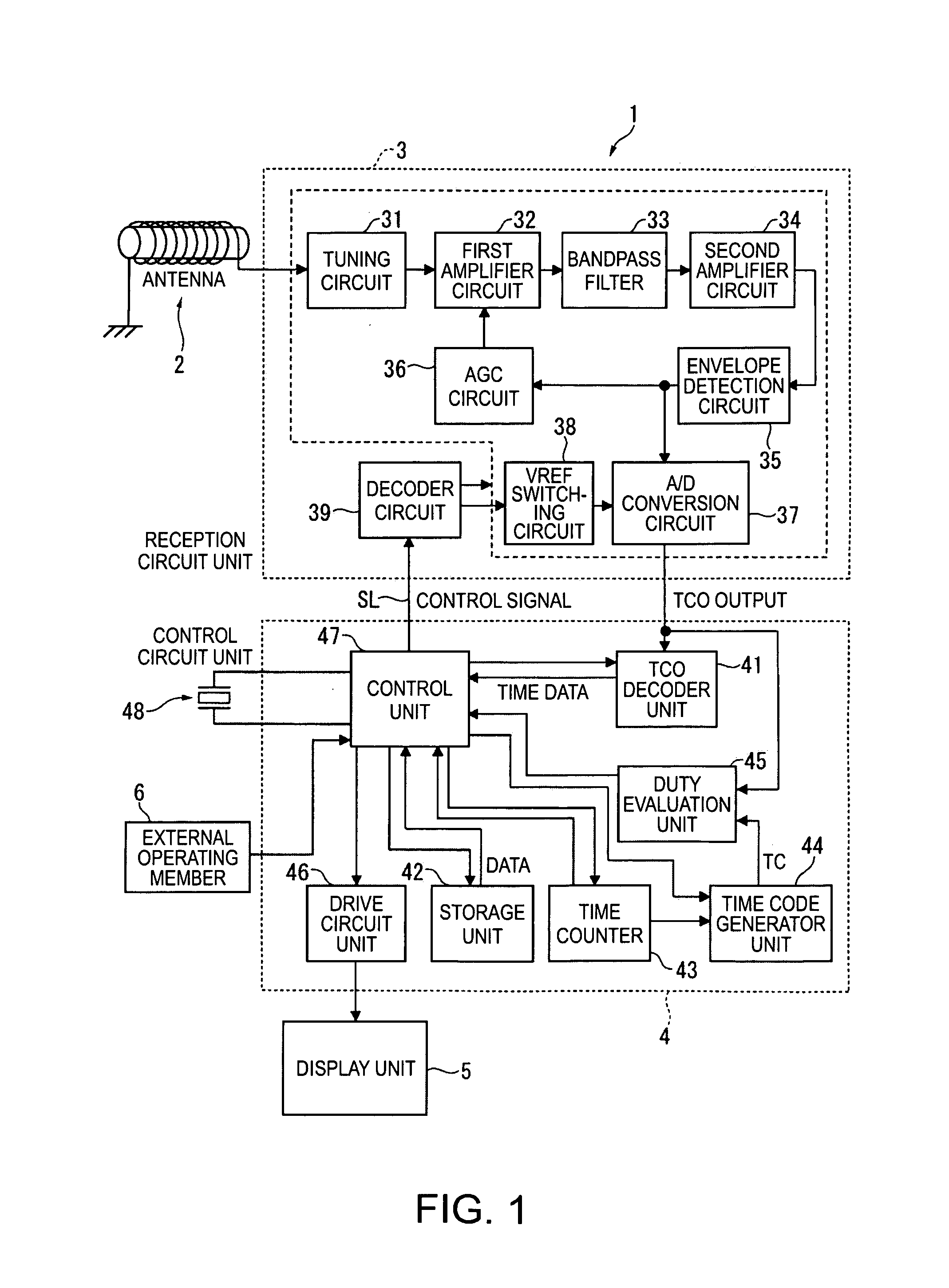
[0076]FIG. 1 is a block diagram showing the configuration of a radio-controlled timepiece according to this first embodiment of the invention.
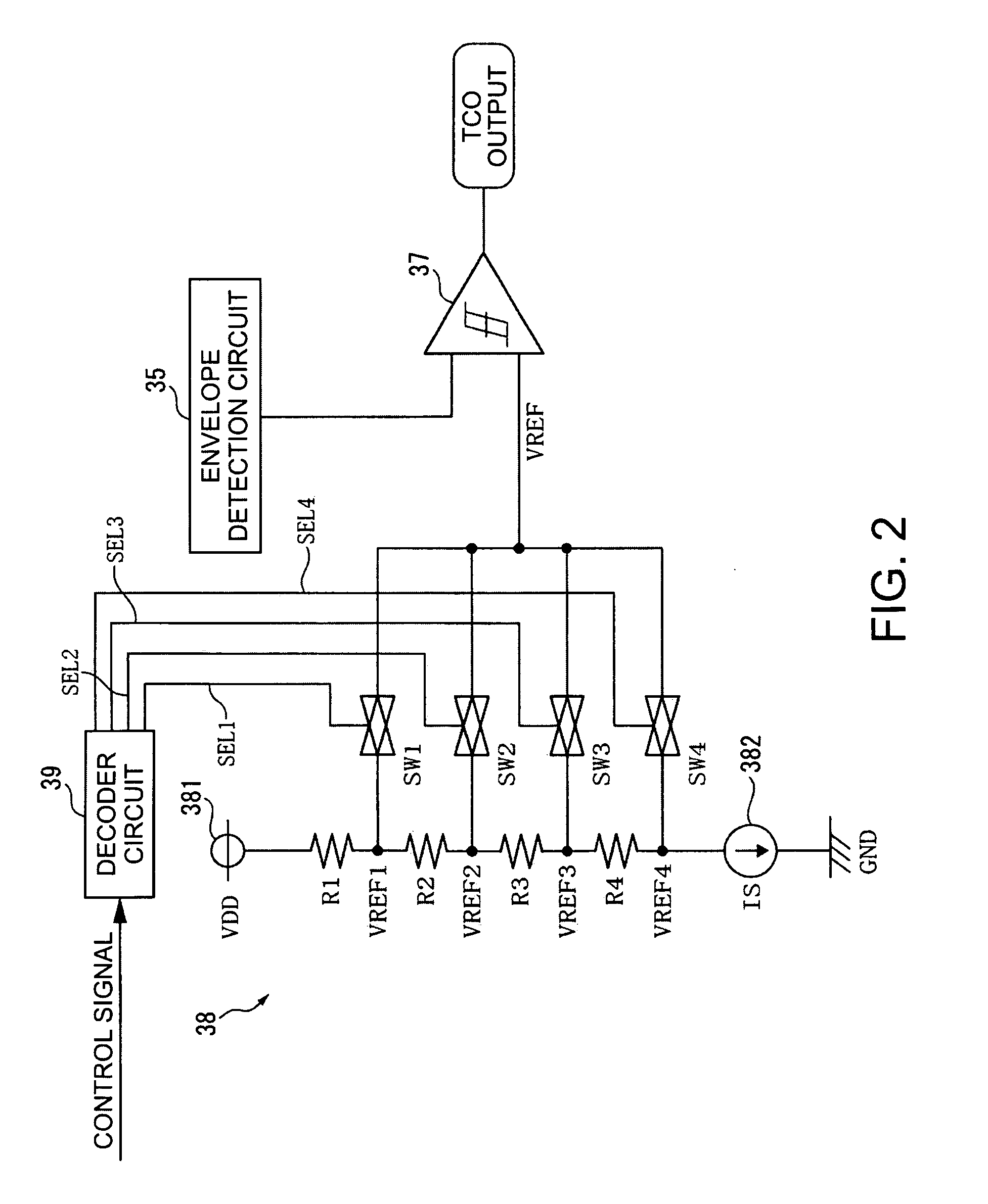
[0077]FIG. 2 is a circuit diagram of the analog / digital (A / D) conversion circuit and VREF switching circuit.
[0078]FIG. 3 shows the duty cycle of the received pulses and the amplitude change in the signals transmitted as part of the JJY standard time signal that is broadcast in Japan.
[0079]FIG. 4 shows the received pulse duty cycle and the amplitude change in the signals transmitted as part of the WWVB standard time signal that is broadcast in the United States.
[0080]FIG. 5 shows the received pulse duty cycle and the amplitude change in the signals transmitted as part of the DCF77 standard time signal that is broadcast in Germany.
[0081]FIG. 6 shows the received pulse duty cycle and the ampl...
embodiment 2
[0176]A radio-controlled timepiece 1A according to a second embodiment of the invention is described next with reference to the accompanying figures.
[0177]FIG. 13 is a block diagram showing the configuration of a radio-controlled timepiece according to this second embodiment of the invention.
[0178]FIG. 14 is a graph of the relationship between gain and the AGC voltage in the first amplifier circuit.
[0179]FIG. 15 is a graph of the relationship between the input level of the reception signal and the AGC voltage at the AGC characteristics that can be selected by the AGC circuit.
[0180]Note that like parts in the radio-controlled timepiece 1A according to this second embodiment of the invention and the radio-controlled timepiece 1 according to the first embodiment described above are identified by the same reference numerals, and further description thereof is omitted or simplified below.
(1) Configuration of the Radio-Controlled Timepiece 1A
[0181]As shown in FIG. 13 the radio-controlled ...
embodiment 3
[0214]A radio-controlled timepiece 1B according to a third embodiment of the invention is described next with reference to the accompanying figures.
[0215]FIG. 18 is a block diagram showing the configuration of a radio-controlled timepiece 1B according to this third embodiment of the invention.
[0216]Note that like parts in the radio-controlled timepiece 1B according to this third embodiment of the invention and the radio-controlled timepieces 1 and 1A according to the foregoing first and second embodiments described above are identified by the same reference numerals, and further description thereof is omitted or simplified below.
(1) Configuration of the Radio-Controlled Timepiece 1B According to the Third Embodiment
[0217]The radio-controlled timepiece 1B according to this third embodiment of the invention differs from the radio-controlled timepiece 1 of the first embodiment in the configuration of the time code generator unit 44.
[0218]More particularly, the time code generator unit ...
PUM
Abstract
A radio-controlled timepiece that receives a standard timesignal containing a time code and adjusts the time based on the received standard timesignal includes: a reception unit that receives the standard timesignal; an analog / digital conversion unit that digitizes the received standard time signal based on a prescribed threshold value; a time counter that keeps time; a time code generator that generates a reference time code based on the time counted by the time counter; a duty evaluation unit that calculates the pulse duty cycle of the digital signal output from the A / D conversion unit, and determines if the received pulse duty cycle that is calculated matches the duty cycle of the reference time code generated by the time code generator; a level changing unit that changes the relative level of the threshold value to the reception signal if the duty evaluation unit determines that the received pulse duty cycle does not match the duty cycle of the reference time code; and a time code decoder that decodes the digital signal and demodulates the time code if the duty evaluation unit determines that the received pulse duty cycle matches the duty cycle of the reference time code.
Description
CROSS-REFERENCE TO RELATED APPLICATIONS[0001]Japanese Patent application No.(s) 2007-181313 and 2008-041877 are hereby incorporated by reference in their entirety.BACKGROUND[0002]1. Field of Invention[0003]The present invention relates to a radio-controlled timepiece that receives a standard time signal containing time information and adjusts the time based on the received standard time signal, and to a control method for the radio-controlled timepiece.[0004]2. Description of Related Art[0005]Radio-controlled timepieces that can receive a standard time signal are known from the literature. See, for example, Japanese Unexamined Patent Appl. Pub. JP-A-H10-274681, and Japanese Unexamined Patent Appl. Pub. JP-A-2006-60849.[0006]The standard time signal is an amplitude modulated signal, and the reception circuit of the radio-controlled timepiece has a filter or other unit of extracting the envelope of the received signal, and an analog / digital conversion circuit that compares the envelop...
Claims
Application Information
Patent Timeline
Application Date:The date an application was filed.
Publication Date:The date a patent or application was officially published.
First Publication Date:The earliest publication date of a patent with the same application number.
Issue Date:Publication date of the patent grant document.
PCT Entry Date:The Entry date of PCT National Phase.
Estimated Expiry Date:The statutory expiry date of a patent right according to the Patent Law, and it is the longest term of protection that the patent right can achieve without the termination of the patent right due to other reasons(Term extension factor has been taken into account ).
Invalid Date:Actual expiry date is based on effective date or publication date of legal transaction data of invalid patent.
