Work carrier and work clamping method using the same

a work carrier and work technology, applied in the field of work carriers, can solve the problems of affecting the smooth and accurate assembling of window glass and other parts relative damage to the vehicle door, and inaccurate assembly of the vehicle door

Inactive Publication Date: 2009-01-15
HONDA MOTOR CO LTD
View PDF3 Cites 9 Cited by
  • Summary
  • Abstract
  • Description
  • Claims
  • Application Information

AI Technical Summary

Benefits of technology

[0020]Since the first slider and the second clamp member are forcibly displaced toward the first clamp member while the second slider remains locked in position on the guide rail via meshing engagement provided between the rack and the toothed portion, it is possible to firmly clamp plate-like work between the clamp member of the fixed clamp unit and the clamp member of the movable clamp unit.

Problems solved by technology

The work carrier of the foregoing construction is not fully satisfactory in that when subjected to a relatively large horizontal force occurring at the starting and stopping of the work carrier, the door is likely to be displaced from a desired clamped position against the force of the compression coil spring, resulting in inaccurate assembly of the vehicle door.
An attempt to increase the spring constant of the compression coil spring may damage the vehicle door.
However, a problem may occur when the screw member 113 on the operation lever 112 comes into meshing engagement with the screw member 114 on the support plate 108.
The thus created space allows horizontal movement or wobbling of the vehicle door occurring during conveyance by the work carrier, which will hinder smooth and accurate assembling of a window glass and other parts relative to the vehicle door.

Method used


Image

  • Work carrier and work clamping method using the same
  • Work carrier and work clamping method using the same
  • Work carrier and work clamping method using the same

Examples


Embodiment Construction

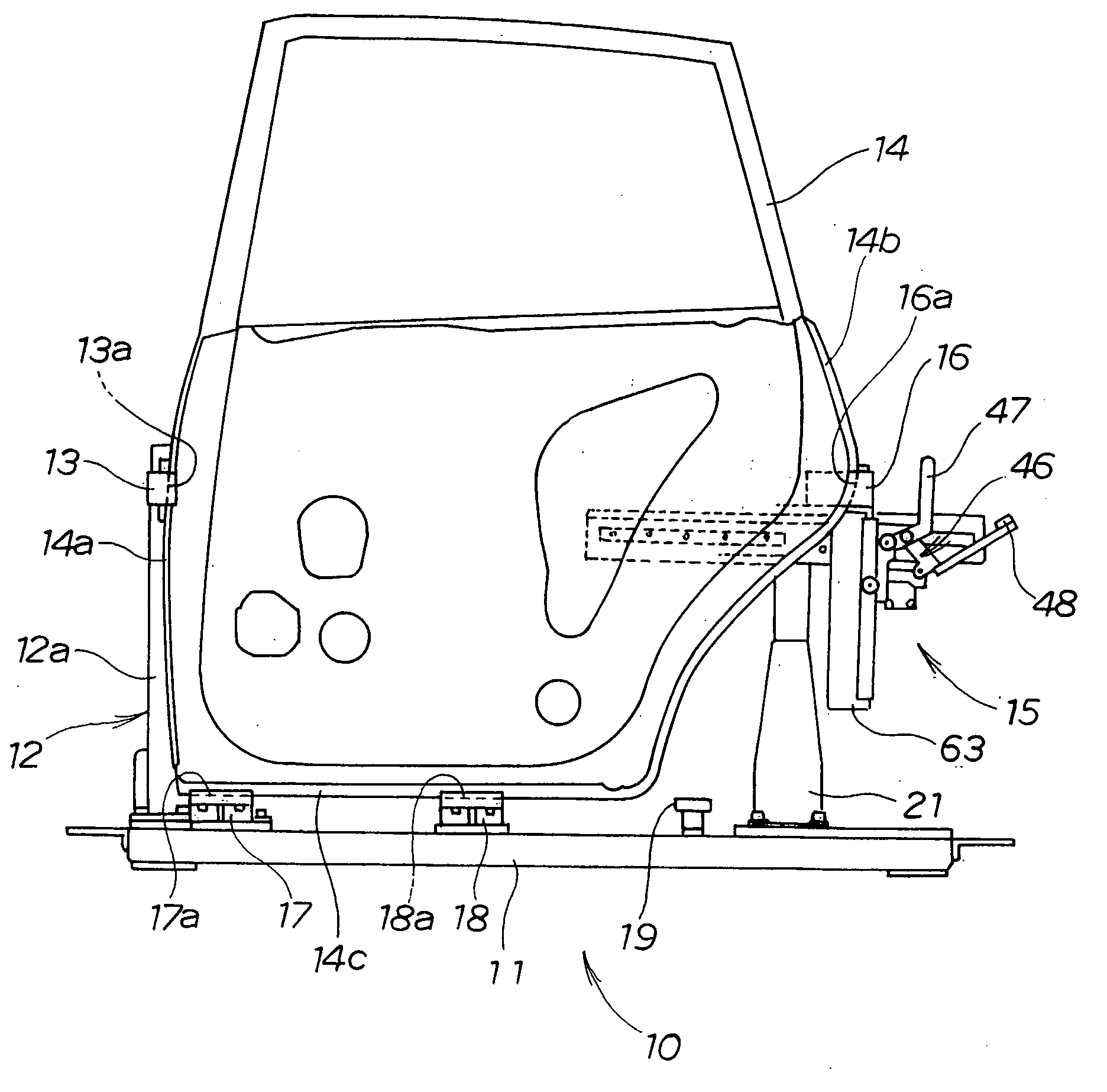
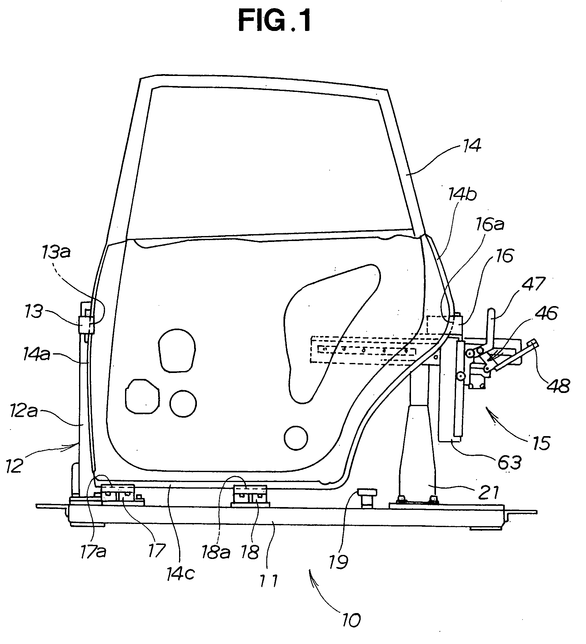
[0032]As shown in FIG. 1, a work carrier 10 embodying the invention takes the form of a door pallet used in an automobile assembly line. The door pallet (work carrier) 10 includes a horizontal base 11, a front clamp unit 12 disposed on one end (left end in FIG. 1) of the base 11 and having a clamp member 13 for holding a front vertical edge 14a of a vehicle door 14, a rear clamp unit 15 disposed on the other end (right end in FIG. 1) of the base 11 and having a clamp member 16 for holding a rear vertical edge 14b of the vehicle door 14, and a plurality (three in the illustrated embodiment) of support members 17, 18 and 19 disposed on the base 11 between the front and rear clamp units 12 and 15 for supporting thereon a lower edge 14c of the vehicle door 14.

[0033]The clamp member 13 of the front clamp unit 12 has a groove 13a facing toward the clamp member 16 of the rear clamp unit 15. The groove 13a has a shape complementary in contour to the shape of the front vertical edge 14a of t...


PUM

PropertyMeasurementUnit
forceaaaaaaaaaa
resiliencyaaaaaaaaaa
distanceaaaaaaaaaa

Abstract

A work carrier includes a movable clamp unit (15) having resiliently connected first and second sliders (26, 27) mounted on a guide rail (24), a lock lever (37) mounted on the second slider and normally urged in a direction to move a toothed portion (41) into meshing engagement with a rack (25), an operating lever (46) pivotally mounted on the second slider, and a cam mechanism (43, 38, 44, 45) operable in response to pivotal movement of the operating lever in one direction such that the second slider is locked in position against movement relative to the guide rail via meshing engagement between the toothed portion and the rack and, subsequently, the first slider and clamp member carried thereon are forcibly displaced away from the second slider while the second slider remains locked on the guide rail.

Description

TECHNICAL FIELD[0001]The present invention relates to a work carrier for carrying a plate-like work, such as vehicle door, with the work held in an upright position and also to a method of clamping the plate-like work using the work carrier.BACKGROUND ART[0002]Work carriers of the type concerned are used in an automobile assembly line for conveyance of a plate-like work, such as vehicle door, to an assembling station where a window glass and other parts are assembled with the door, or to a desired station in another processing line. Typical examples of such work carriers are disclosed in Japanese Utility Model Registration No. 2571180 (corresponding to JP 6001158U) and Japanese Patent Laid-Open Publication No. HEI 11-348777 (JP 1134877 A).[0003]The work carrier disclosed in JP 6001158U includes a fixed clamp member disposed on a base and a movable clamp member disposed via a bracket on the base so that a vehicle door can be clamped at opposite vertical edges thereof by and between t...

Claims


Application Information

Patent Timeline
Patent Type & Authority Applications(United States)
IPC IPC(8): B65G37/00
CPCB62D65/06Y10T29/53978Y10T29/53961
Inventor SUGA, FUMIAKITSUJI, TOSHIHIROMAEDA, MITSUOWAKABAYASHI, YUICHI
Owner HONDA MOTOR CO LTD
Why Eureka
Try Eureka