
Image auto-calibration method and system

Inactive Publication Date: 2009-01-15
HOLTEK SEMICON
View PDF10 Cites 3 Cited by
  • Summary
  • Abstract
  • Description
  • Claims
  • Application Information

AI Technical Summary

Benefits of technology

[0006]It is an aspect of the present invention to provide an image auto-calibration method and system for solving problems of high cost and time waste of the image adjustments for image capture devices.
[0011]Preferably, the image auto-calibration method further comprises a step of eliminating a part of the sampling pulse sets in advance so as to reduce a calculating time for the eigenvalues.

Problems solved by technology

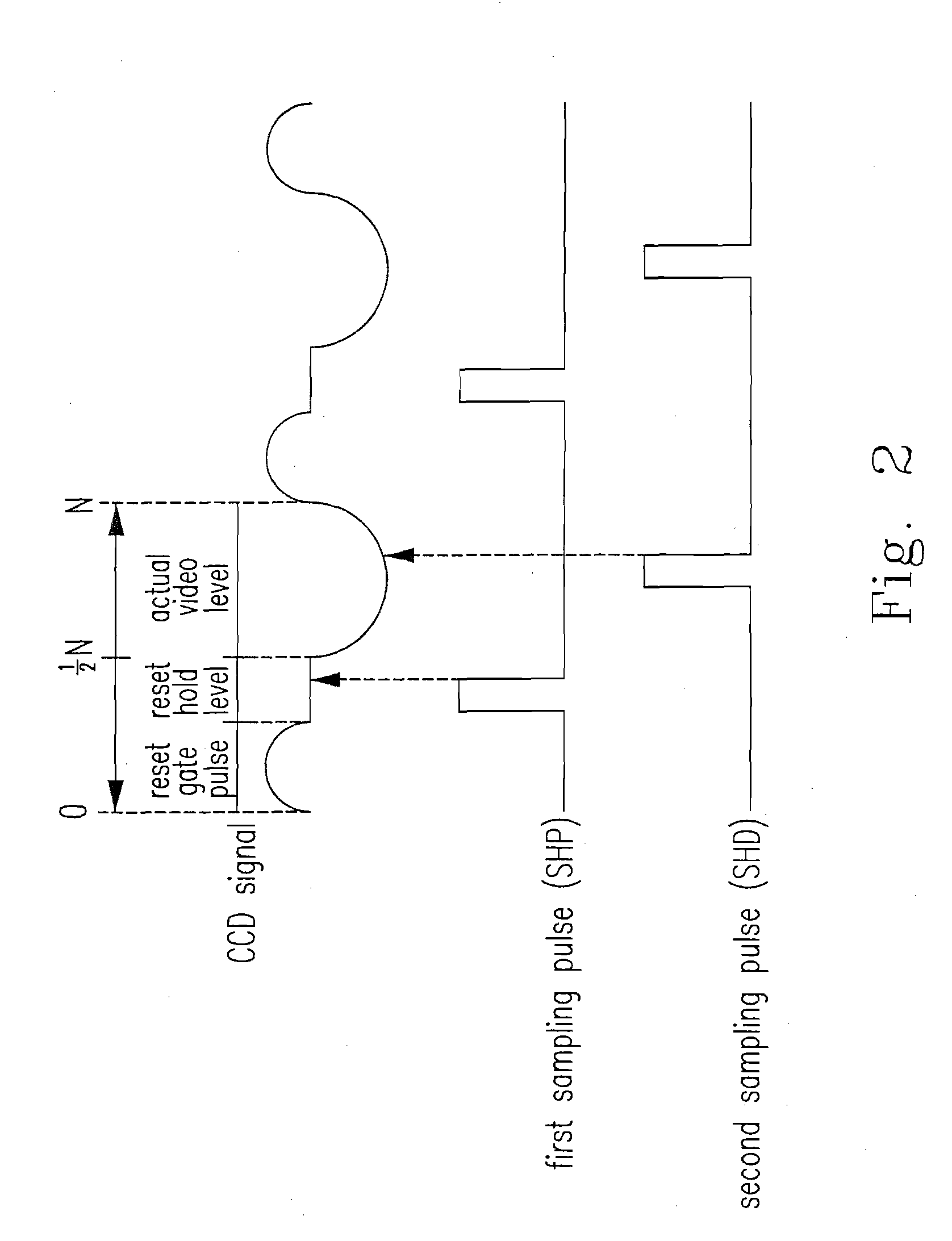
However, because the processes of integrated circuits and print circuits are hard to maintain stable and identical, the adjustment in the sample-and hold pulses (SHP, SHD) for accurately matching the timing of the output of the image signals is usually required.
This adjusting method not only wastes time and cost, but also lacks an identical reference standard for the image adjustment.
However, this method not only has high cost, but also cannot find an optimal timing for the best sampling point automatically.

Method used


Image

  • Image auto-calibration method and system
  • Image auto-calibration method and system
  • Image auto-calibration method and system

Examples


Embodiment Construction

[0033]The present invention will now be described more specifically with reference to the following embodiments. It is to be noted that the following descriptions of preferred embodiments of this invention are presented herein for the purposes of illustration and description only; it is not intended to be exhaustive or to be limited to the precise form disclosed.

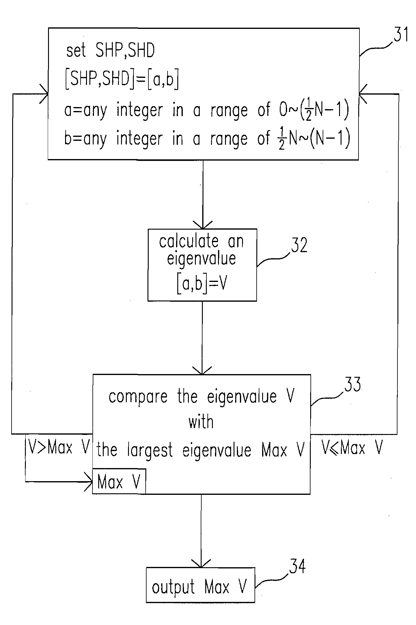
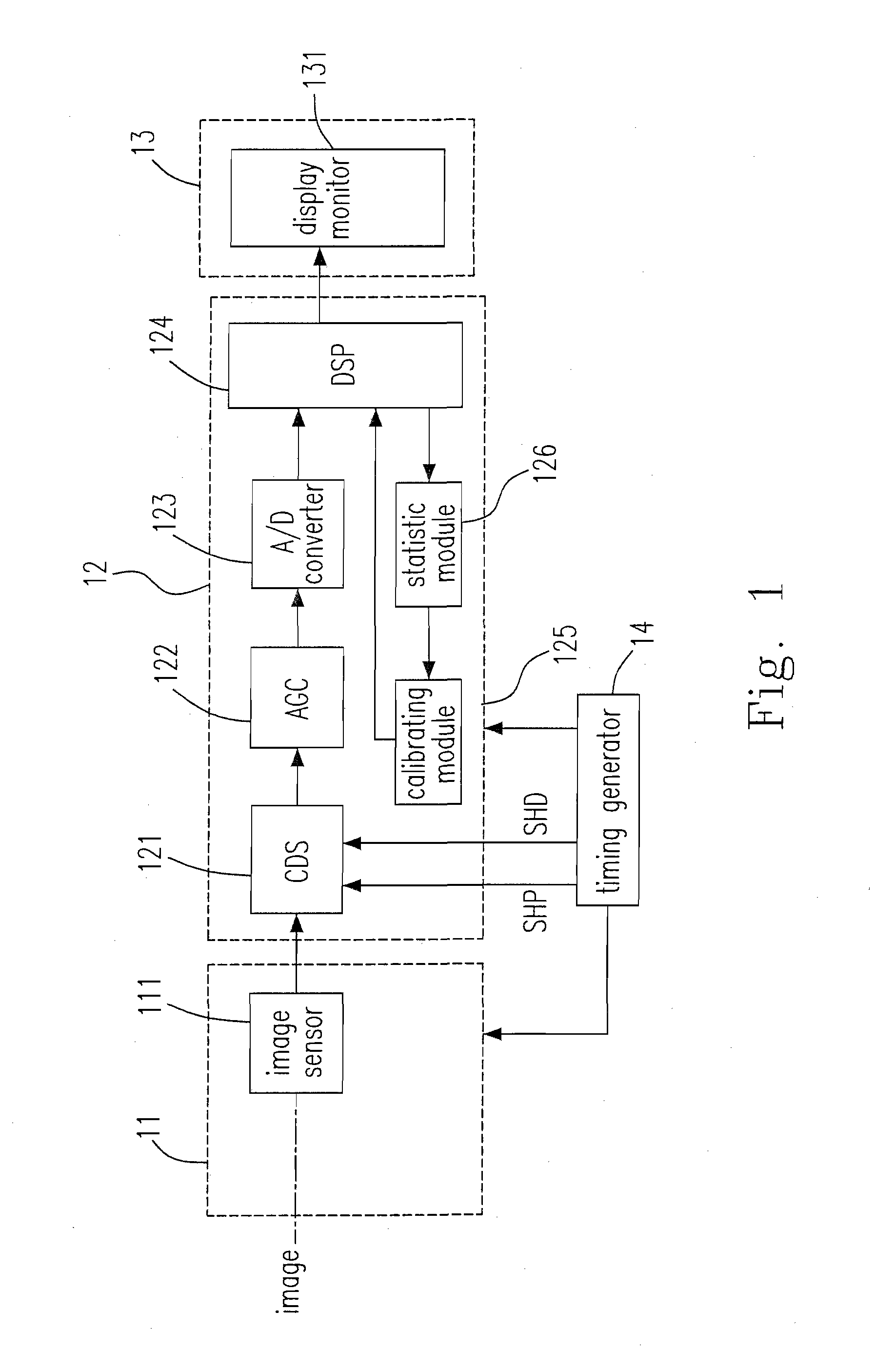
[0034]Please refer to FIG. 1, which is a diagram showing the image capture device in the present invention. The image capture device comprises an image capture module 11 for capturing an image, an image processing module 12 and an image display module 13 for displaying the image according to a sampling pulse set. The image auto-calibration system of the present invention is configured in the image capture device and comprises a statistic module 126 and a calibrating module 125. The image capture module 11 comprises an image sensor 111 for sensing a focussed image and converting it into an image signal, wherein the image inpu...


PUM


Abstract

An image auto-calibration method for an image capture device having an image sensor is provided. The method includes the steps of receiving an image matrix; transforming the image matrix into an image signal via the image sensor; generating n first sampling pulses and n second sampling pulses in response to the image signal, wherein one of the first sampling pulses and one of the second sampling pulses constitute a sampling pulse set; calculating an eigenvalue of the image signal according to each of the sampling pulse sets; and outputting an image according to the sampling pulse set with the largest eigenvalue.

Description

FIELD OF THE INVENTION[0001]The present invention relates to an image auto-calibration method and system, and more particularly to an image auto-calibration method and system for an image capture device.BACKGROUND OF THE INVENTION[0002]The growth in the consumer market of the multimedia is tremendous in recent years and the charge-coupled device (CCD) is widely used in the multimedia for serving as their image sensor. During the process of an image capture in a CCD system, the image transmitted to the CCD is converted into electrical signals and output from the CCD. After sampled, the electrical signals will be processed in an image processor. At last, the processed signals are output from the image processor and displayed on a display monitor according to the sampling. In brief, the CCD system converts a light energy into an electrical energy by the way of “sampling”, and thus finding an optimal timing for the best sampling point of the output signals of the CCD is the most fundame...

Claims


Application Information

Patent Timeline
IPC IPC(8): G03B43/00H04N5/222
CPCH04N17/002H04N23/00H04N25/46H04N25/60
Inventor WENG, JEN-CHUNGTSAI, CHIEN-HSIEN
Owner HOLTEK SEMICON
Learn More