Chemical solution vaporizing tank and chemical solution treating system

a technology of chemical solution and vaporizing tank, which is applied in the direction of chemical vapor deposition coating, liquid surface applicator, coating, etc., can solve the problems of deterioration of the wafer effect, reducing the freshness of the solution, and lowering the concentration, so as to suppress the difference in the concentration of the processing gas

Active Publication Date: 2009-01-22
TOKYO ELECTRON LTD
View PDF11 Cites 398 Cited by
  • Summary
  • Abstract
  • Description
  • Claims
  • Application Information

AI Technical Summary

Benefits of technology

[0008]The invention has been made in view of the above circumstances, and an object of the invention is to provide a chemical solution vaporizing tank and a chemical solution processing system in which a processing gas is produced by supplying a vaporization gas (i.e., a gas for vaporization) to a chemical solution stored in the chemical solution vaporizing tank, and is supplied to a work (i.e., an object to be processed), and particularly is to suppress a difference in concentration of the processing gases to be supplied to the plurality of works, respectively.

Problems solved by technology

As a time elapses since the solution such as the HMDS was supplied into the chemical solution vaporizing tank, a degree of freshness of the solution decreases, and the concentration lowers due to decomposition so that the effect thereof on the wafer deteriorates.
This increases a space required for installing these hydrophobic processing systems, and thus disadvantageously increases the installation space of the developing device.
However, the respective chambers of the tank are connected to the processing modules by pipes, and difference in pressure loss in the pipe usually occur between the pipes due to differences in diameter and / or length between the pipes.
Thereby, a ratio between the chemical solution and the gas varies in each chamber, and consequently the vaporization efficiency varies in each chamber independently of the other chambers so that differences occur between the concentrations of the HMDS gas supplied to the respective modules, resulting in a problem that the control becomes impossible.

Method used


Image

  • Chemical solution vaporizing tank and chemical solution treating system
  • Chemical solution vaporizing tank and chemical solution treating system
  • Chemical solution vaporizing tank and chemical solution treating system

Examples


Embodiment Construction

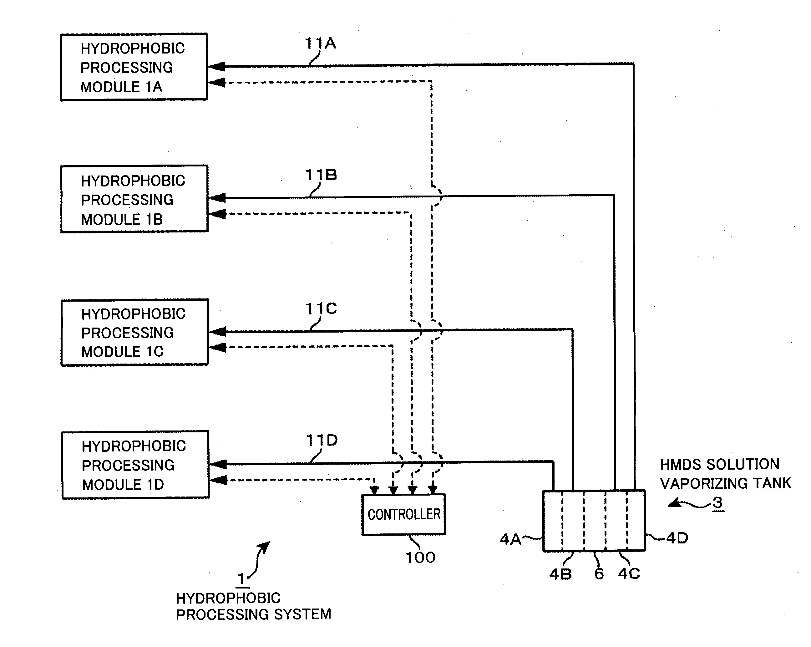
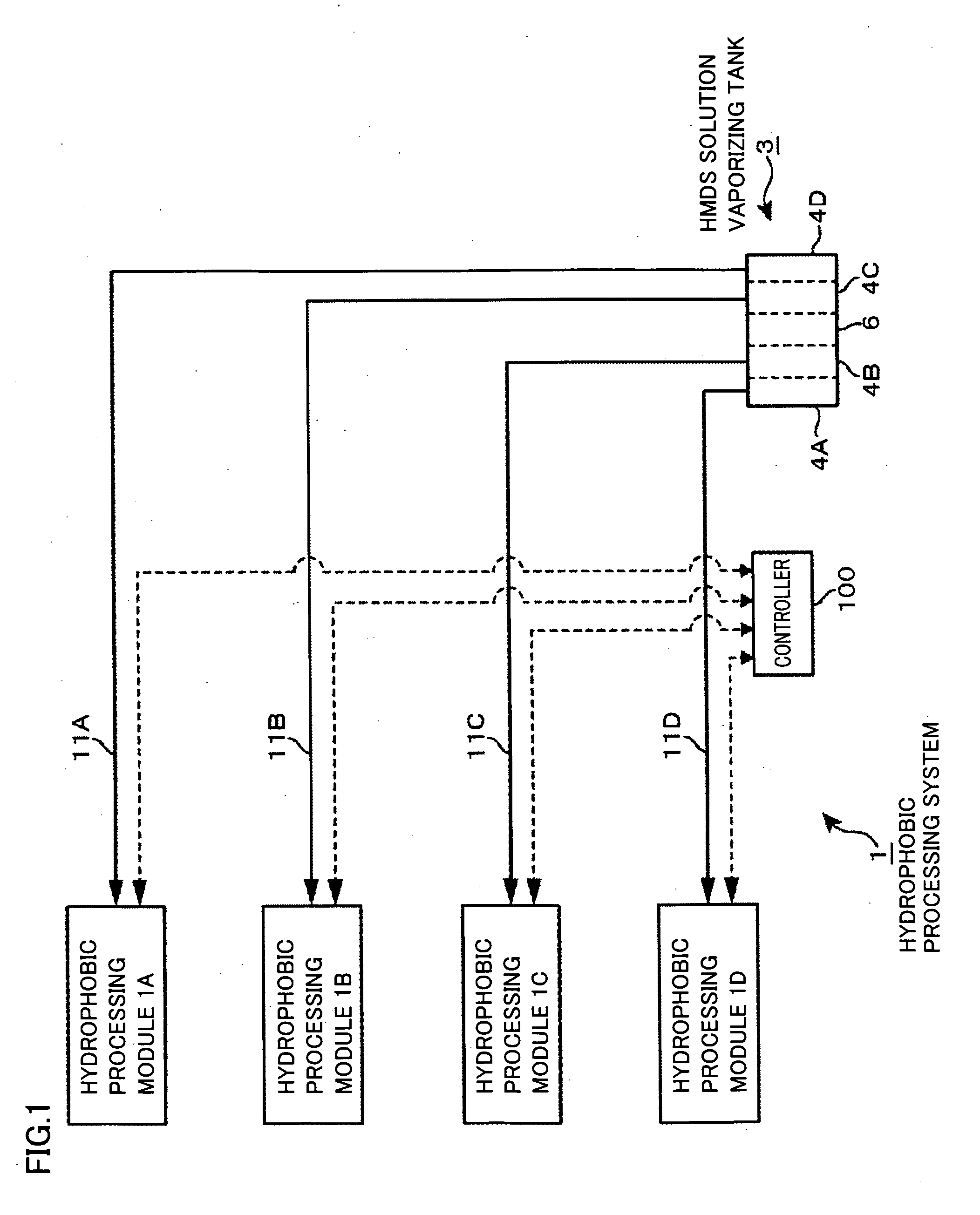
[0025]A hydrophobic processing system 1 that is a chemical solution processing system including an HMDS solution vaporizing tank 3 for vaporizing a HMDS solution (i.e., a chemical solution) will be described below as an example of an embodiment of a chemical solution vaporizing tank of the invention. FIG. 1 is a schematic view of hydrophobic processing system 1. Hydrophobic processing system 1 includes hydrophobic processing modules 1A, 1B, 1C and 1D, which are connected via gas supply pipes 11A, 11B, 11C and 11D to vaporizing chambers 4A, 4B, 4C and 4D arranged in chemical solution vaporizing tank 3, respectively.

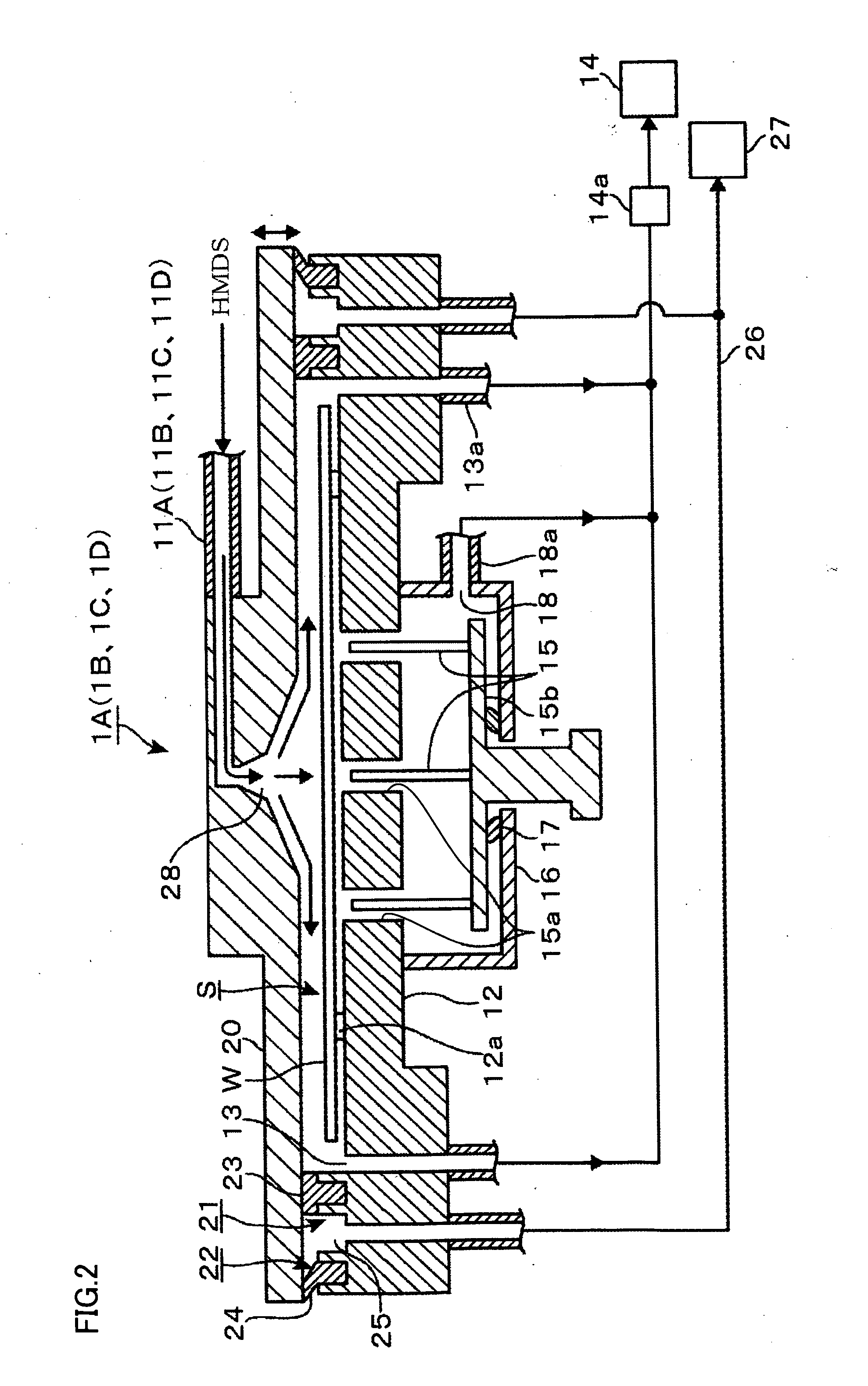
[0026]Hydrophobic processing modules 1A-1D will be described below. Hydrophobic processing modules 1A-1D and hydrophobic processing module 1A will now be described by way of example with reference to FIG. 2. Hydrophobic processing module 1A includes a table 12, and four (only two is shown in FIG. 2) projections 12a that are spaced from each other, e.g., in a circumferentia...


PUM

PropertyMeasurementUnit
diameteraaaaaaaaaa
diameteraaaaaaaaaa
pressuresaaaaaaaaaa

Abstract

An object is to suppress differences in concentration between processing gases supplied to a plurality of works in a chemical solution vaporizing tank. The chemical solution vaporizing tank includes a tank body having a plurality of vaporizing chambers formed by laterally and airtightly partitioning an internal space of the tank body, a chemical solution passage located under a liquid level in each vaporizing chamber and formed at each partition member for passing the chemical solution between the vaporizing chambers, and a gas passage located above the liquid level in each vaporizing chamber and formed at the partition member to communicate the vaporizing chambers with each other for uniformizing pressures in the respective vaporizing chambers. A quantity of the channel layer in each vaporizing chamber is controlled by managing, e.g., the liquid level.

Description

BACKGROUND OF THE INVENTION[0001]1. Field of the Invention[0002]The present invention relates to a chemical solution vaporizing tank and a chemical solution processing system for producing a processing gas by supplying a vaporization gas (i.e., a gas for vaporization) to a stored chemical solution and supplying the processing gas to a work for processing it.[0003]2. Description of the Background Art[0004]In a photoresist step that is one of semiconductor manufacturing steps, a resist pattern is formed by applying resist over a surface of a semiconductor wafer that is a substrate (and will be referred to as a “wafer” hereinafter), exposing the resist with a predetermined pattern and then developing it. This processing is generally performed with a system in which an exposing device is connected to a coating and developing device performing the coating and development of the resist.[0005]The coating and developing devices may be provided with various liquid processing devices that per...

Claims


Application Information

Patent Timeline
Patent Type & Authority Applications(United States)
IPC IPC(8): C23C16/00B05C11/10
CPCH01L21/67017
Inventor MIZUNAGA, KOUICHIKUDOH, HIROYUKIOOSHIMA, KAZUHIKO
Owner TOKYO ELECTRON LTD
Why Eureka
Try Eureka