

Working liquid for latent heat transport apparatus and method for operating latent heat transport apparatus
Inactive Publication Date: 2009-01-22
ASAHI GLASS CO LTD
View PDF10 Cites 2 Cited by
- Summary
- Abstract
- Description
- Claims
- Application Information
AI Technical Summary
Benefits of technology
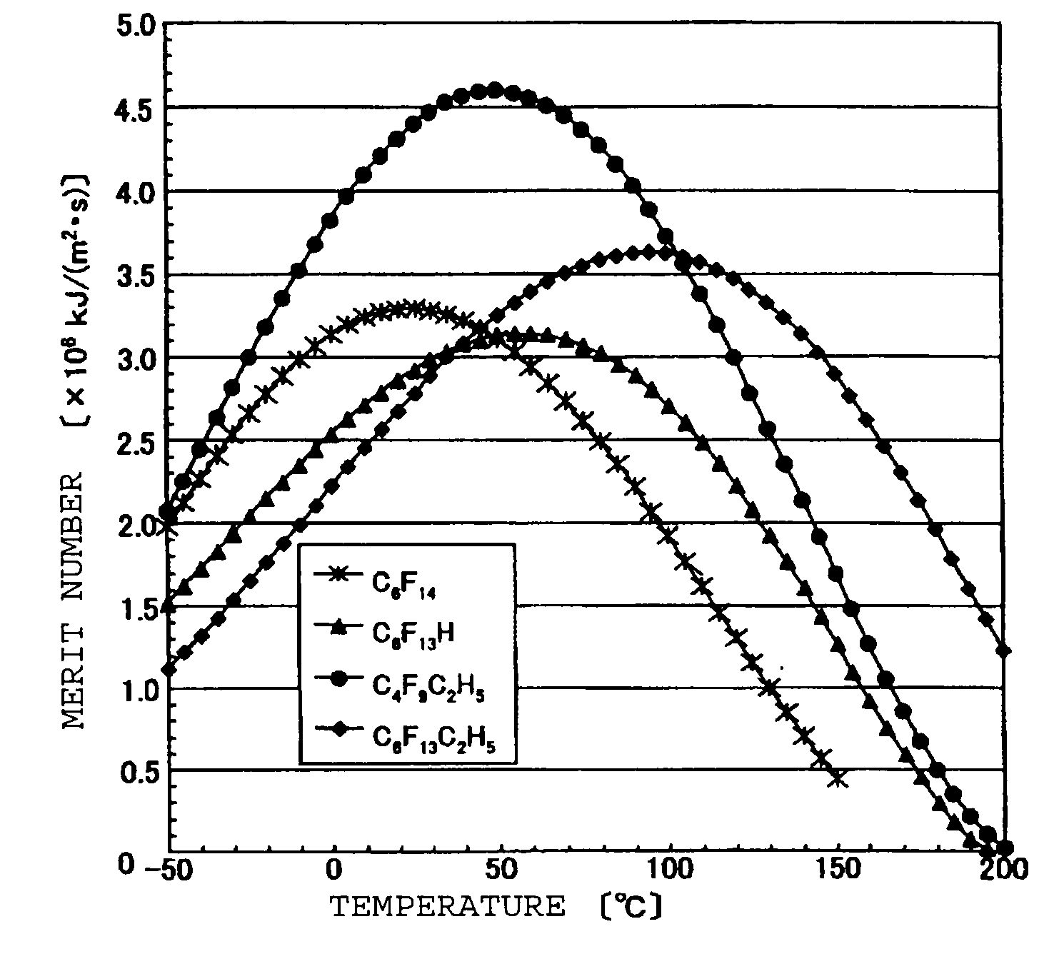
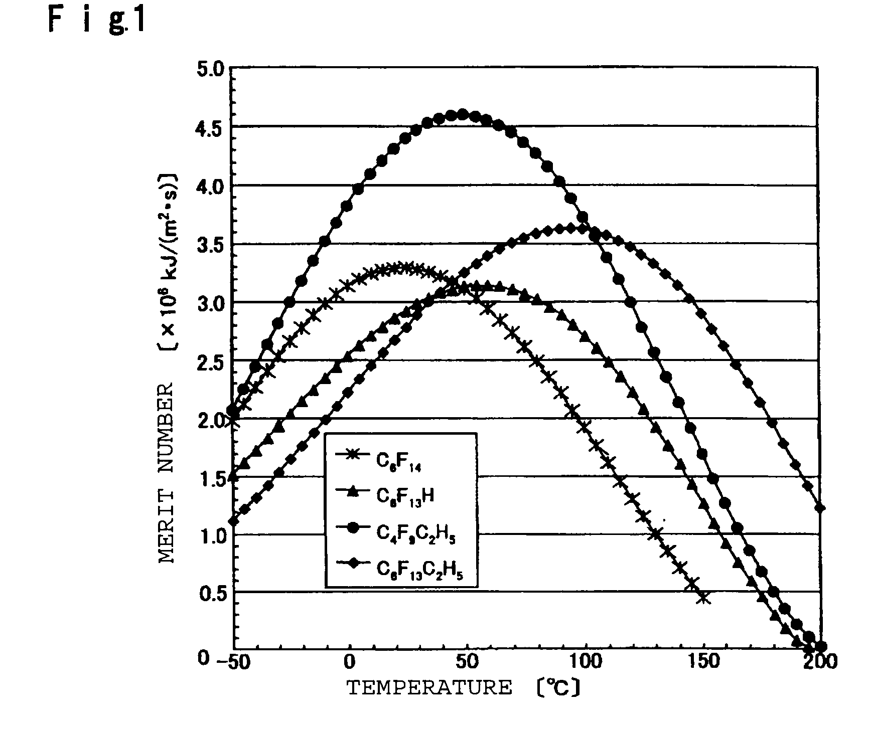
[0026]The working liquid for a latent heat transport apparatus of the present invention has a relatively high merit number and is remarkably excellent in heat conductivity, as compared to conventional working liquids. Further, the working liquid for a latent heat transport apparatus of the present invention has a high antioxidation property and anti-corrosion property to stainless steel or aluminum used as a material of latent heat transport apparatuses. Further, it has an advantage that it can be used for conventional systems as it is. Further, it is free from environmental problems such as destruction of an ozone layer and global warming.
Problems solved by technology
However, in the case of water, there is a problem of freezing in cold district.
Whereas, in the case of ammonia, not only conformity with a heat pipe container is required, but also handling is cumbersome due to a bad smell and toxicity.
In the case of methanol, there is a problem of corrosion of an aluminum or stainless steel container.
However, heat conductivities of these working liquids are poor, and there is a problem of global warming.
Method used
View moreImage
Smart ImageViewing Examples

Examples
example 1
[0057](Example of the present invention): the working liquid is C4F9C2H5
example 2
[0058](Example of the present invention): the working liquid is C6F13C2H5
example 3
[0059](Comparative Example): the working liquid is C6F14 (n-perfluorohexane)
Login to View More PUM
 Abstract
To provide a working liquid for a latent heat transport apparatus which is free from environmental problems such as destruction of an ozone layer and global warming and which shows a high performance constantly at an operation temperature of from −50 to 200° C.A working liquid for a latent heat transport apparatus, which comprises a compound represented by the following formula 1:CnF2n+1—CmH2m+1 Formula 1,wherein n is an integer of from 2 to 8, and m is an integer of from 1 to 3. A method for operating a latent heat transport apparatus which employs the above working liquid, characterized in that the operation temperature is from −50 to 200° C.
Description
TECHNICAL FIELD[0001]The present invention relates to a working liquid for a latent heat transport apparatus and a method for operating a latent heat transport apparatus which employs the working liquid.BACKGROUND ART[0002]Latent heat transport apparatuses have been known wherein latent heat transport is carried out by utilizing phenomena of evaporation, boiling, condensation, etc. of a working liquid sealed into the apparatuses. The latent heat transport apparatus may, for example, be a heat pipe or a double phase closed type heat siphon. The heat pipe is an apparatus which transports heat by utilizing capillary force obtained by an internally installed wig (capillary structure), and the double phase closed type heat siphon is an apparatus which transports heat by utilizing gravity and centrifugal force. They are characterized in that a working liquid can be circulated without using an external power such as a pump.[0003]The heat pipe is applied to relatively small refrigerators su...
Claims
Login to View More Application Information
Patent Timeline
 IPC IPC(8): F28D15/00
CPCC09K5/10F28F23/00H01L23/427H01L2924/0002H01L2924/00
InventorFUKUSHIMA, MASATO
OwnerASAHI GLASS CO LTD