

Working liquid for latent heat transport apparatus and method for operating latent heat transport apparatus
a technology of latent heat transport and working liquid, which is applied in the direction of lighting and heating apparatus, machine/engine, and semiconductor/solid-state device details. it can solve the problems of aluminum or stainless steel container corrosion, cumbersome handling, and low heat conductivity, and achieve excellent heat conductivity, high merit number, and high antioxidation and corrosion properties.
Inactive Publication Date: 2012-12-11
AGC INC
View PDF21 Cites 3 Cited by
- Summary
- Abstract
- Description
- Claims
- Application Information
AI Technical Summary
Benefits of technology
The solution offers high heat transport capacity, excellent heat conductivity, antioxidation, and anti-corrosion properties, while being environmentally friendly and suitable for a wide temperature range from -50 to 200°C, avoiding ozone layer destruction and global warming.
Problems solved by technology
However, in the case of water, there is a problem of freezing in cold district.
Whereas, in the case of ammonia, not only conformity with a heat pipe container is required, but also handling is cumbersome due to a bad smell and toxicity.
In the case of methanol, there is a problem of corrosion of an aluminum or stainless steel container.
However, heat conductivities of these working liquids are poor, and there is a problem of global warming.Patent Document 1: JP-A-59-12288 (claims)Patent Document 1: JP 2726542 (claims)
Method used
View moreImage
Smart ImageViewing Examples

Examples
example 1
Example of the Present Invention
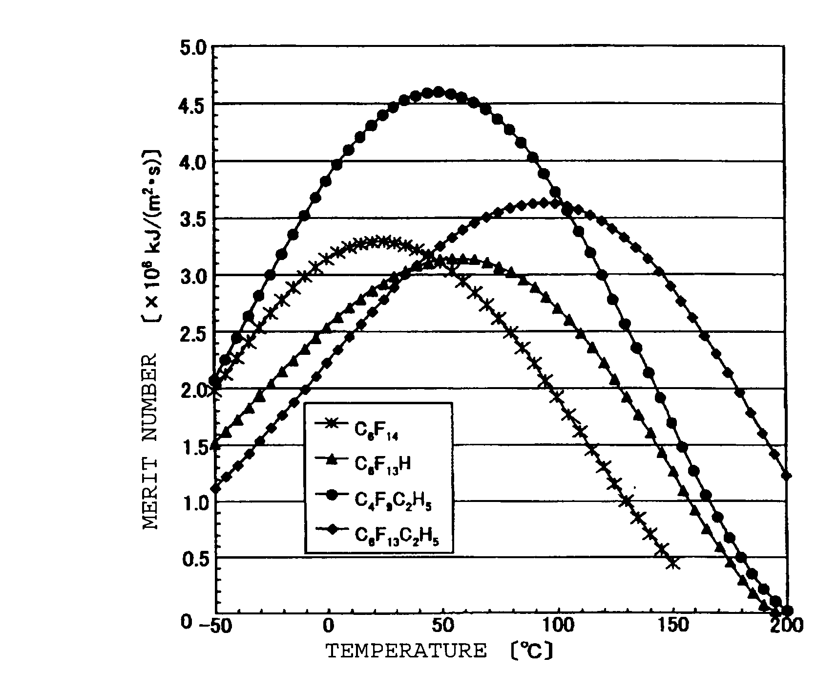
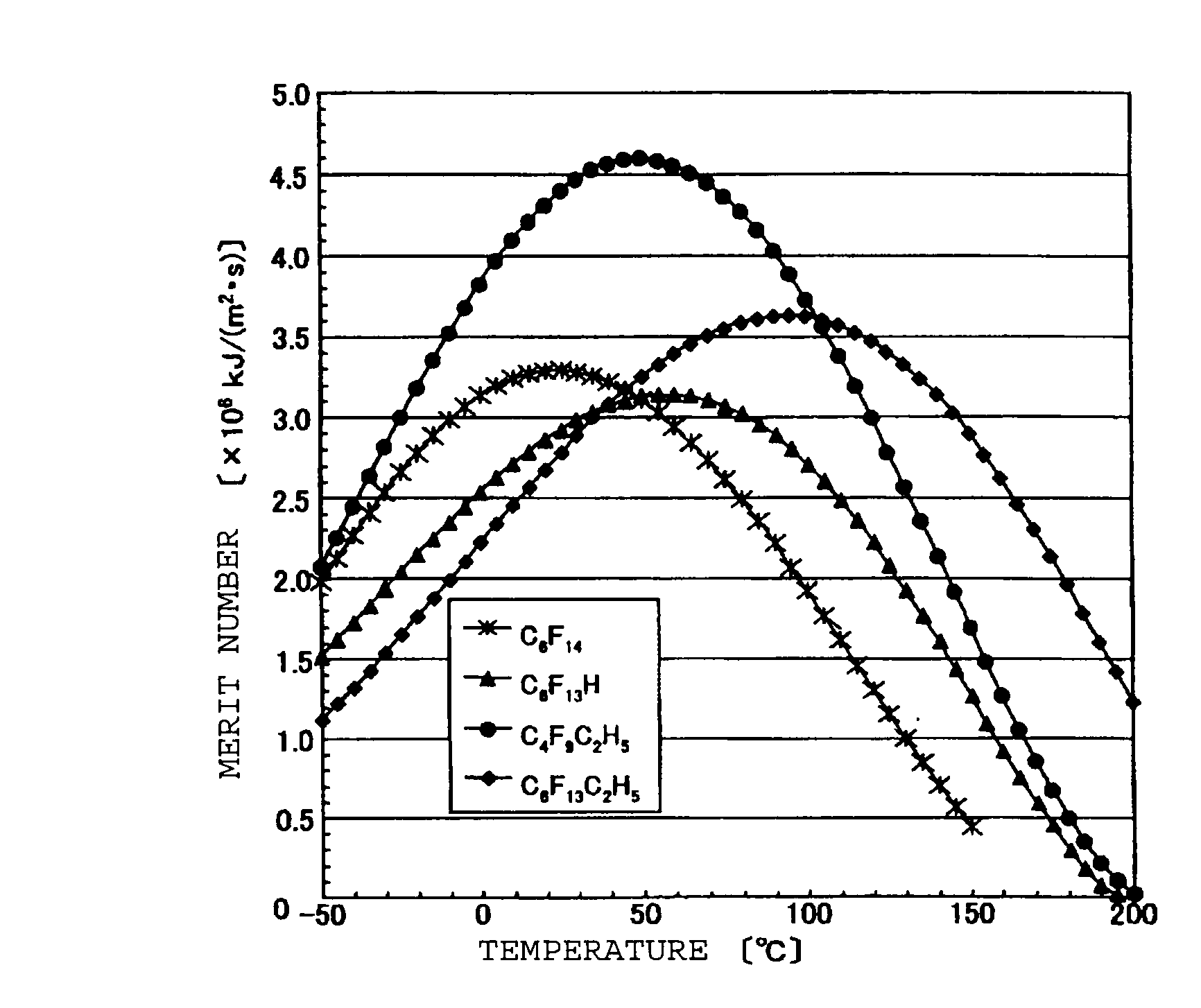
[0058]the working liquid is C4F9C2H5
example 2
Example of the Present Invention
[0059]the working liquid is C6F13C2H5
Login to View More PUM
| Property | Measurement | Unit |
|---|---|---|
| temperature | aaaaa | aaaaa |
| vapor temperature | aaaaa | aaaaa |
| boiling point | aaaaa | aaaaa |
Abstract
A method for operating a latent heat transport apparatus by providing a working liquid for a latent heat transport apparatus, which includes a compound of the formula C6F13C2H5 at an operation temperature of from −50 to 200° C.
Description
CROSS REFERENCE TO RELATED APPLICATIONS[0001]The present application is the bypass continuing application of international application PCT / JP2007 / 057683, filed on Apr. 5, 2007, and claims the benefit of the filing date of Japanese Application No. 2006-105312, filed on Apr. 6, 2006.TECHNICAL FIELD[0002]The present invention relates to a working liquid for a latent heat transport apparatus and a method for operating a latent heat transport apparatus which employs the working liquid.BACKGROUND ART[0003]Latent heat transport apparatuses have been known wherein latent heat transport is carried out by utilizing phenomena of evaporation, boiling, condensation, etc. of a working liquid sealed into the apparatuses. The latent heat transport apparatus may, for example, be a heat pipe or a double phase closed type heat siphon. The heat pipe is an apparatus which transports heat by utilizing capillary force obtained by an internally installed wig (capillary structure), and the double phase clos...
Claims
Login to View More Application Information
Patent Timeline
 Patent Type & AuthorityPatents(United States)
IPC IPC(8): C09K5/04
CPCC09K5/10F28F23/00H01L23/427H01L2924/0002H01L2924/00
InventorFUKUSHIMA, MASATO
OwnerAGC INC