High heat conduction composite material

a composite material and high heat conduction technology, applied in the direction of rigid containers, synthetic resin layered products, packaging, etc., can solve the problems of difficult to improve the heat conductivity to a great extent, invite aggravating economic properties, and short fibrous carbon materials, etc., to achieve excellent electric conduction, heat conductivity, and excellent durability. , the effect of excellent corrosion resistan

Inactive Publication Date: 2010-06-10
LOCAL INC ADMINISTATIVE AGENCY TECH RES INST OF OSAKA PREFECTURE +1
View PDF7 Cites 11 Cited by
  • Summary
  • Abstract
  • Description
  • Claims
  • Application Information

AI Technical Summary

Benefits of technology

[0042]By using a metal such as pure aluminum, an aluminum alloy, or titanium or ceramics being excellent in corrosion resistance or a heat dissipation property as a substrate, the high heat conduction composite material of the present invention can take advantage of the corrosion property inherently owned by these materials themselves or the excellent durability under a high temperature environment. By compounding and integrating a fibrous carbon material into this material, the excellent electric conduction, heat conductivity, and the strength owned by the fibrous carbon material itself can be combined, whereby an increase in the desired properties, a synergistic effect, or a novel function can be manifested. By using a mixture obtained by mixing a small amount of a small diameter fiber into a large diameter fiber as the fibrous carbon material, a high-performance thermal network by the fibrous carbon material can be constructed, whereby the heat conduction function and the like can be manifested in a particularly effective manner. Also, by restraint of the amount of use of the fibrous carbon material, the economical property can also be enhanced.
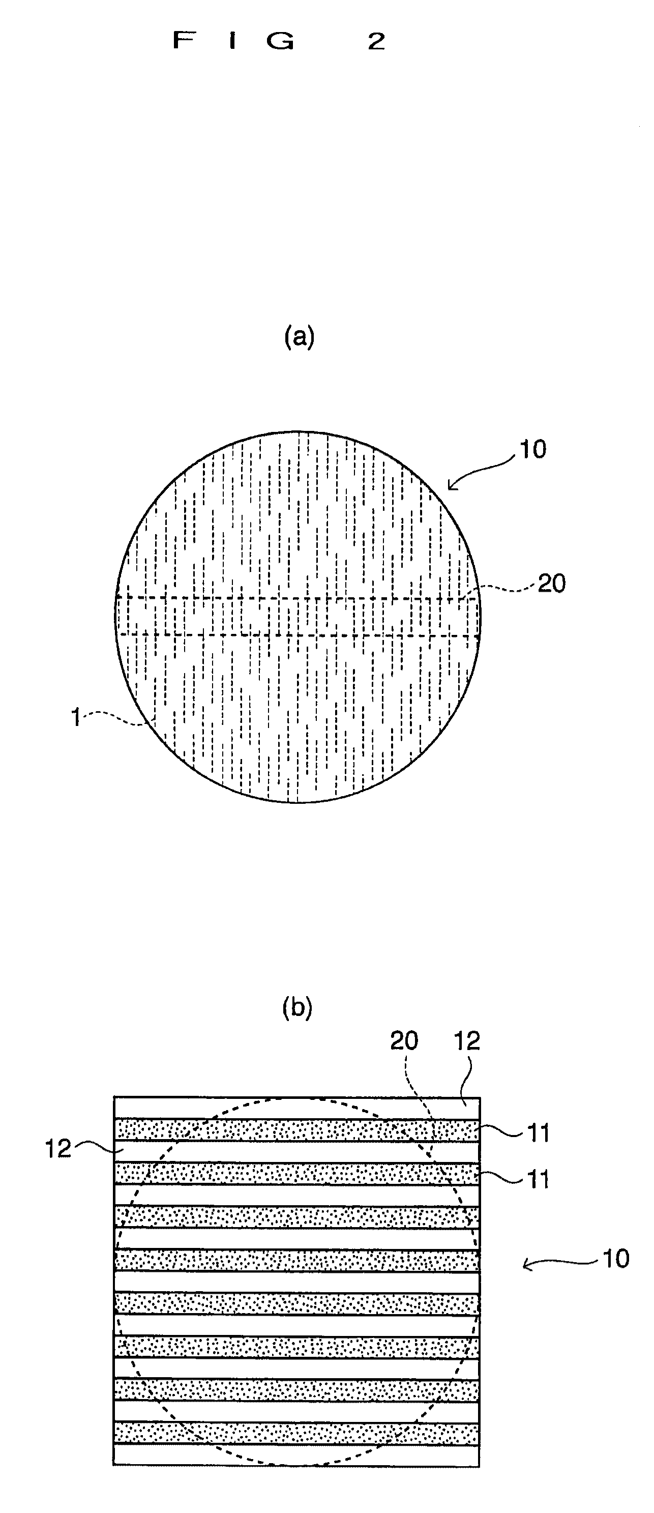
[0043]Hereafter, an embodiment of the present invention will be described. In the present embodiment, a carbon material-containing metal material of fiber lamination type is produced in which sheets made of a fibrous carbon material are arranged at a predetermined interval within a spark plasma sintered body of a metal powder, a mixed powder of a metal and ceramics, or a ceramic powder.
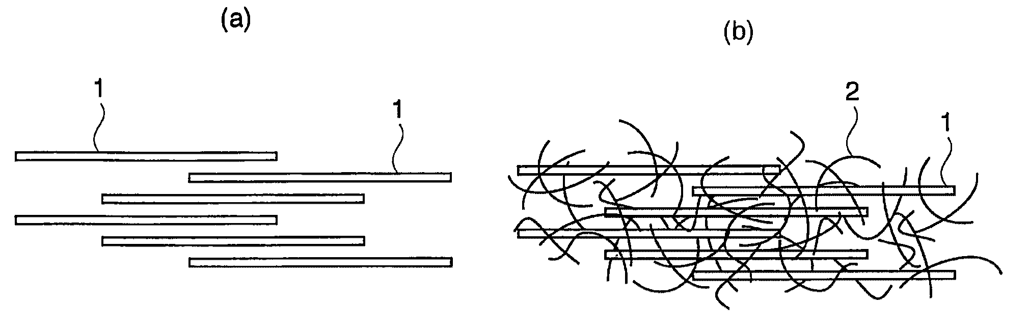
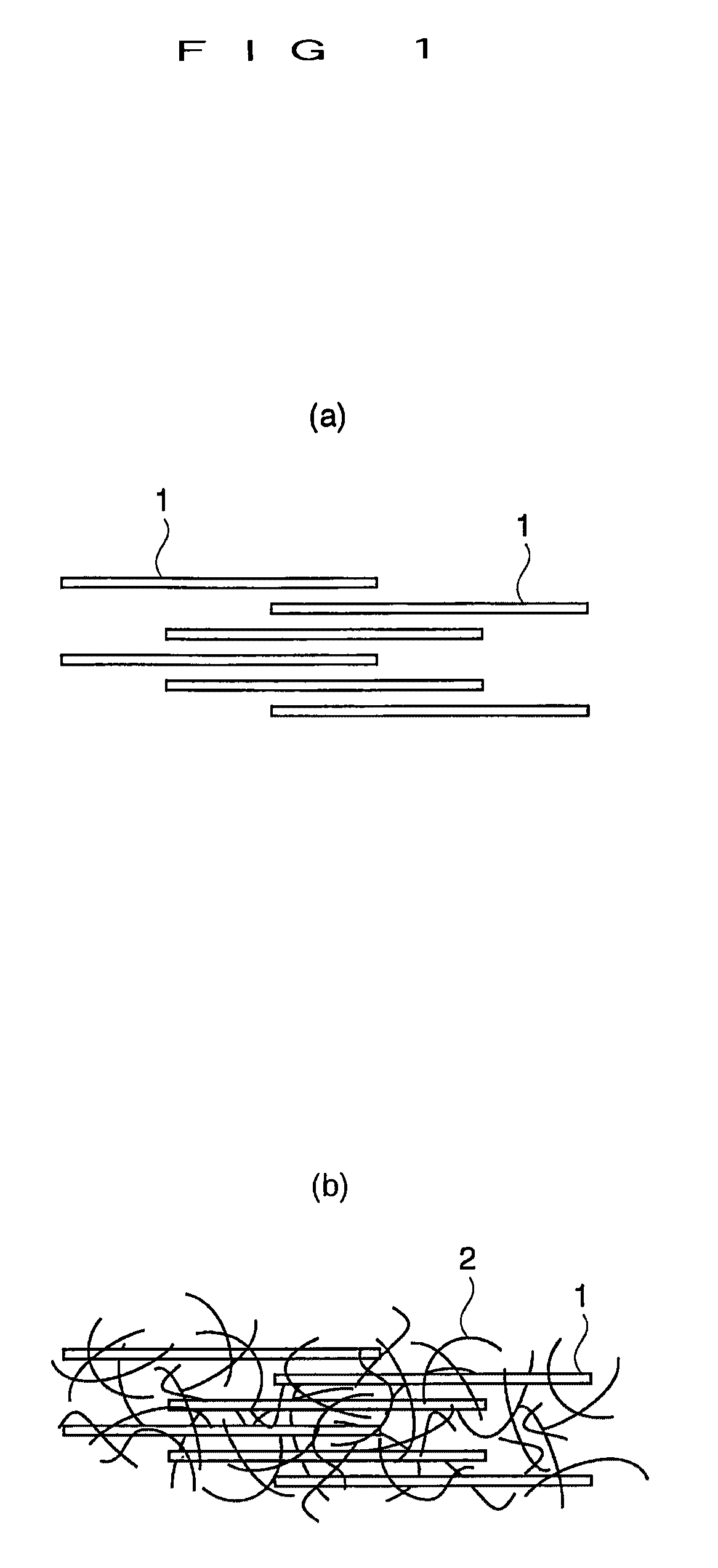
[0044]In this method, first, a sheet of a fibrous carbon material that will be a fiber layer is fabricated. Specifically, a mixed fiber sheet is fabricated in which a large diameter fiber and a small diameter fiber are mixed at a predetermined ratio. More specifically, a mixed fiber sheet is fabricated in which a large diameter fiber is oriented. What is important here is that only the large diameter fiber is oriented, and the small diameter fiber is not oriented. For this purpose, first, an orientation base sheet is made with the large diameter fiber. The orientation base sheet may be one that is naturally produced during the vapor growth process. Alternatively, it is also possible to make the orientation base sheet by applying a magnetic field or an electric field to the dispersion liquid of the large diameter fiber. It is also possible to form a base sheet in which the large diameter fiber is oriented in a specific direction by a physical method such as a method of putting a dispersion liquid into an ejection device such as an injection syringe and extruding the liquid in plural lines along one direction, a method of allowing the dispersion liquid to flow along a standing plate, or a method of immersing a plate into a dispersion liquid and slowly pulling up the plate.
[0045]A mixed sheet of fiber orientation type is fabricated by allowing a small diameter fiber to adhere in a non-oriented manner onto a base sheet of fiber orientation type fabricated in this manner. Before or after forming the fibrous carbon material into a sheet, spark plasma processing can be performed on the fibrous carbon material, and it will be described later in detail that this processing is effective for an elongation function of the fibrous carbon material, surface activation, diffusion of a powder substance, and the like.
[0046]The orientation base sheet will be further described in detail. A vapor growth carbon fiber representative as a large diameter fiber is produced by simultaneously vapor-growing numerous lines from a substrate surface with use of a catalyst. As a result of this, the vapor growth carbon fiber is produced in a mode in which numerous lines of fibers are densely gathered in a two-dimensional manner on the substrate. The numerous lines of fibers densely gathered in a two-dimensional manner are in many cases in a state of having fallen down in one direction by a gas flow during the production process, and a fiber sheet oriented in one direction can be obtained simply by separating the densely gathered fiber from the substrate. This can be used, as it is, as a base sheet made of the large diameter fiber, or can be used after being lightly pressed. If the fibers are not fallen down, a base sheet oriented in one direction can be obtained by letting the fibers fall down in one direction with use of a roller or the like.
[0047]As another method of making a mixed fiber sheet, for example, a large diameter fiber and a small diameter fiber are mixed in advance at a predetermined ratio to form a dispersion liquid thereof, which is then thinly solidified to fabricate the mixed sheet. Besides mixing the large diameter fiber and the small diameter fiber at the stage of the dispersion liquid, it is also possible to fabricate a mixed fiber sheet by making a base sheet in advance with a large diameter fiber and allowing a small diameter fiber to adhere to this base sheet.

Problems solved by technology

However, the fibrous carbon material is essentially short and is not continuous in one direction.
Therefore, even if it could be oriented in one direction, it would be difficult to improve the heat conductivity to a great extent.
However, even with that vapor growth carbon fiber, a large amount of vapor growth carbon fiber is needed to improve the heat conductivity to a great extent, thereby inviting aggravation of economical property.
However, even with a vapor growth carbon fiber, a fibrous carbon material is essentially expensive.
A long one having a high straightness property is developed; however, a long one is especially expensive.

Method used


Image

  • High heat conduction composite material
  • High heat conduction composite material
  • High heat conduction composite material

Examples


examples

[0059]Next, the effect of the present invention will be made clear by specific examples. As a metal powder, an aluminum powder having an average particle size of 30 μm was prepared. As a fibrous carbon material, an orientation sheet of a vapor growth carbon fiber and a carbon nanotube having a thickness of 1 to 50 nm (30 nm on average) and a length of several hundred μm were prepared. The orientation sheet of the vapor growth carbon fiber is a densely gathered body of the vapor growth carbon fiber having a thickness of 1 to 50 μm (10 μm on average) and a length of about 2 to 3 mm, and is a fiber orientation sheet having a thickness in the order of 100 μm in which the direction of the fiber orientation is the same direction parallel to the surface. As described above, such an orientation sheet is produced naturally during the vapor growth process.

[0060]Carbon nanotubes are collected by cropping those that have vertically grown from numerous points on the substrate surface. This was d...


PUM

PropertyMeasurementUnit
diameteraaaaaaaaaa
diameteraaaaaaaaaa
particle sizeaaaaaaaaaa

Abstract

A composite material being excellent in heat conductivity is provided. In order to realize this, a fibrous carbon material made of fine tube form structures constituted with single-layer or multiple-layer graphene is present to form a plurality of layers within a substrate made from a spark plasma sintered body of a metal powder, a mixed powder of a metal and ceramics, or a ceramic powder. The fibrous carbon material constituting each layer is made of a mixture obtained by mixing a small amount of a small diameter fiber 2 having an average diameter of 100 nm or less with a large diameter fiber 1 having an average diameter of 500 nm to 100 μm.

Description

TECHNICAL FIELD[0001]The present invention relates to a highly functional high heat conduction composite material endowed with excellent heat conductivity, electric conductivity, mechanical properties, and others in addition to various features inherently owned by a substrate, by mixing a fibrous carbon material such as a vapor growth carbon fiber (VGCF) with a substrate made from a metal material or a ceramics material.BACKGROUND ART[0002]As the fibrous carbon material, a carbon nanotube (CNT) and a vapor growth carbon fiber (VGCF) are well known. Both the carbon nanotube and the vapor growth carbon fiber are fine tube form structures constituted with graphene, and are differentiated by the difference in the lamination structure and the fiber diameter associated therewith, as will be described below.[0003]Graphene is a net of honeycomb structure in which six carbon atoms are regularly arranged in a two-dimensional manner, and is also referred to as a carbon hexagonal net plane. The...

Claims


Application Information

Patent Timeline
Patent Type & Authority Applications(United States)
IPC IPC(8): B32B5/02
CPCB32B5/02Y10T428/139B82Y40/00C01B31/0206C04B35/645C04B35/83C04B2235/5264C04B2235/5268C04B2235/5272C04B2235/5288C04B2235/666C04B2235/9607C22C47/14C22C49/02C22C49/06C22C49/08C22C49/11Y10S977/742Y10S977/776Y10S977/777Y10T428/1393Y10T428/1397B82Y30/00B32B5/30B32B2262/106B32B2264/105B32B2264/107B32B2307/302B32B2307/306B32B2307/714B32B2457/00C04B35/111C04B35/486C04B35/5607C04B35/5611C04B35/5626C04B35/565C04B35/58014C04B35/58071C04B35/58078C04B35/581C04B35/587C04B35/80C04B2235/5248C04B2235/526C22C47/025C22C49/14C01B32/15Y10T428/249927Y10T428/249928Y10T428/249929Y10T428/24995
Inventor KATAGIRI, KAZUAKISHIMIZU, AKIYUKIIMANISHI, TERUMITSUSATO, TOYOHIRONAKAMA, NOBUHITOKAKITSUJI, ATSUSHISASAKI, KATSUHIKO
Owner LOCAL INC ADMINISTATIVE AGENCY TECH RES INST OF OSAKA PREFECTURE
Why Eureka
Try Eureka