Lubrication apparatus

Inactive Publication Date: 2009-01-22
TOYOTA JIDOSHA KK
View PDF2 Cites 20 Cited by
  • Summary
  • Abstract
  • Description
  • Claims
  • Application Information

AI Technical Summary

Benefits of technology

[0112]As described above, the present invention introduces the return oil, which flows back from the lubrication target mechanism, to the first and second chambers via the first and second oil return paths. Therefore, the return oil is stored in the second chamber as well. After termination of a warm-up operation

Problems solved by technology

Consequently, the oil stored in the second chamber of the apparatus is not readily used for oil circulation between the engine block a

Method used


Image

  • Lubrication apparatus
  • Lubrication apparatus
  • Lubrication apparatus

Examples


sixth embodiment

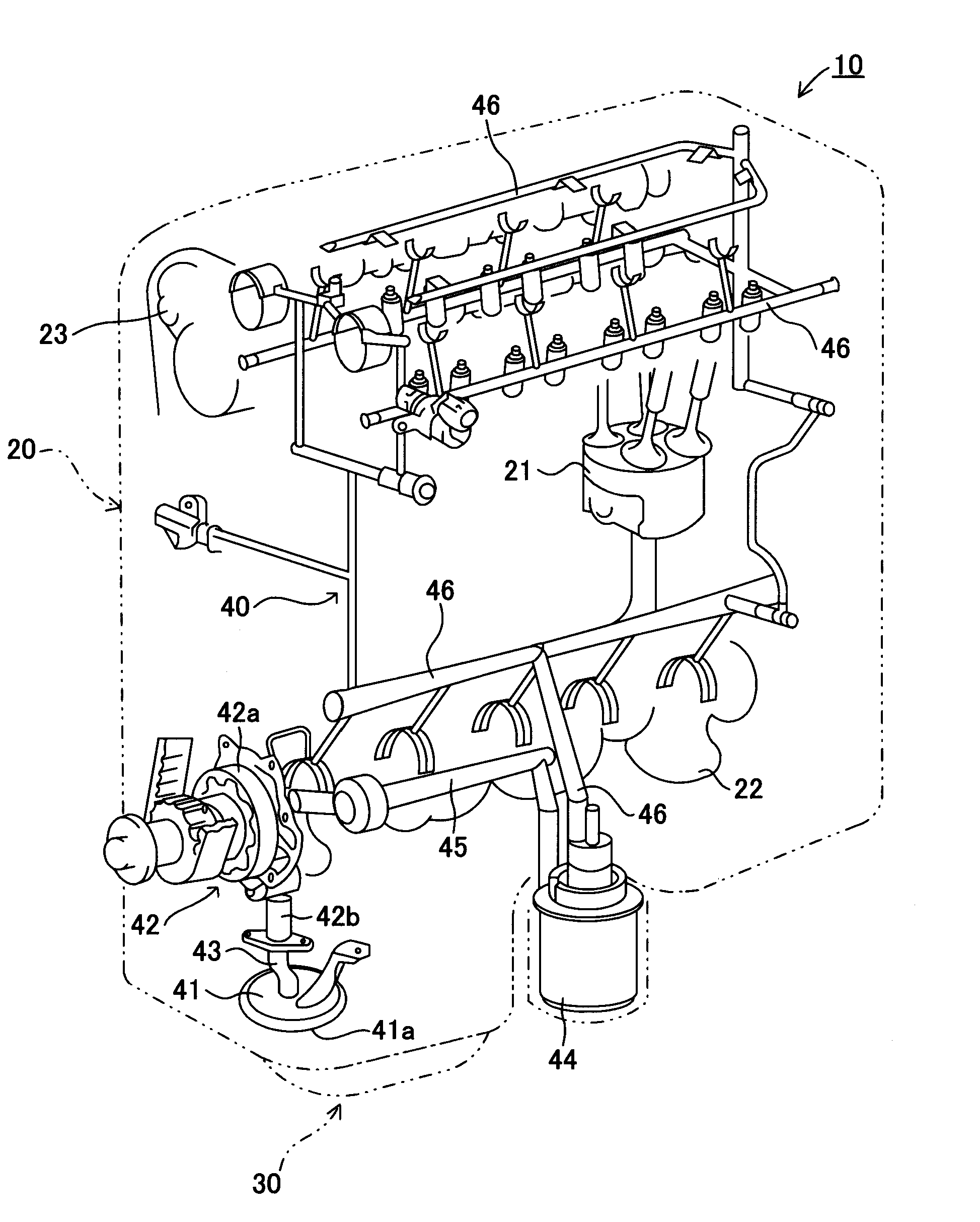
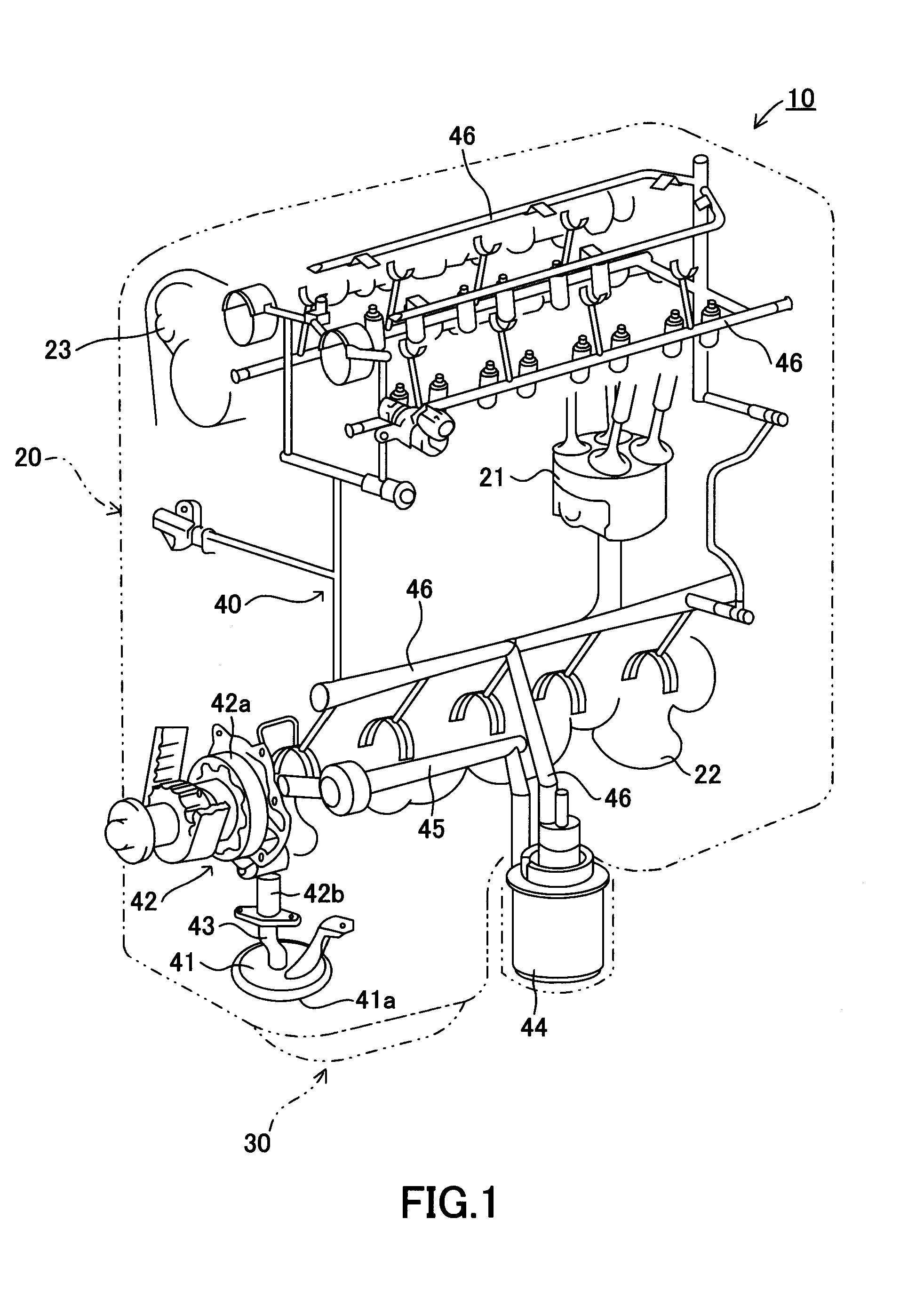
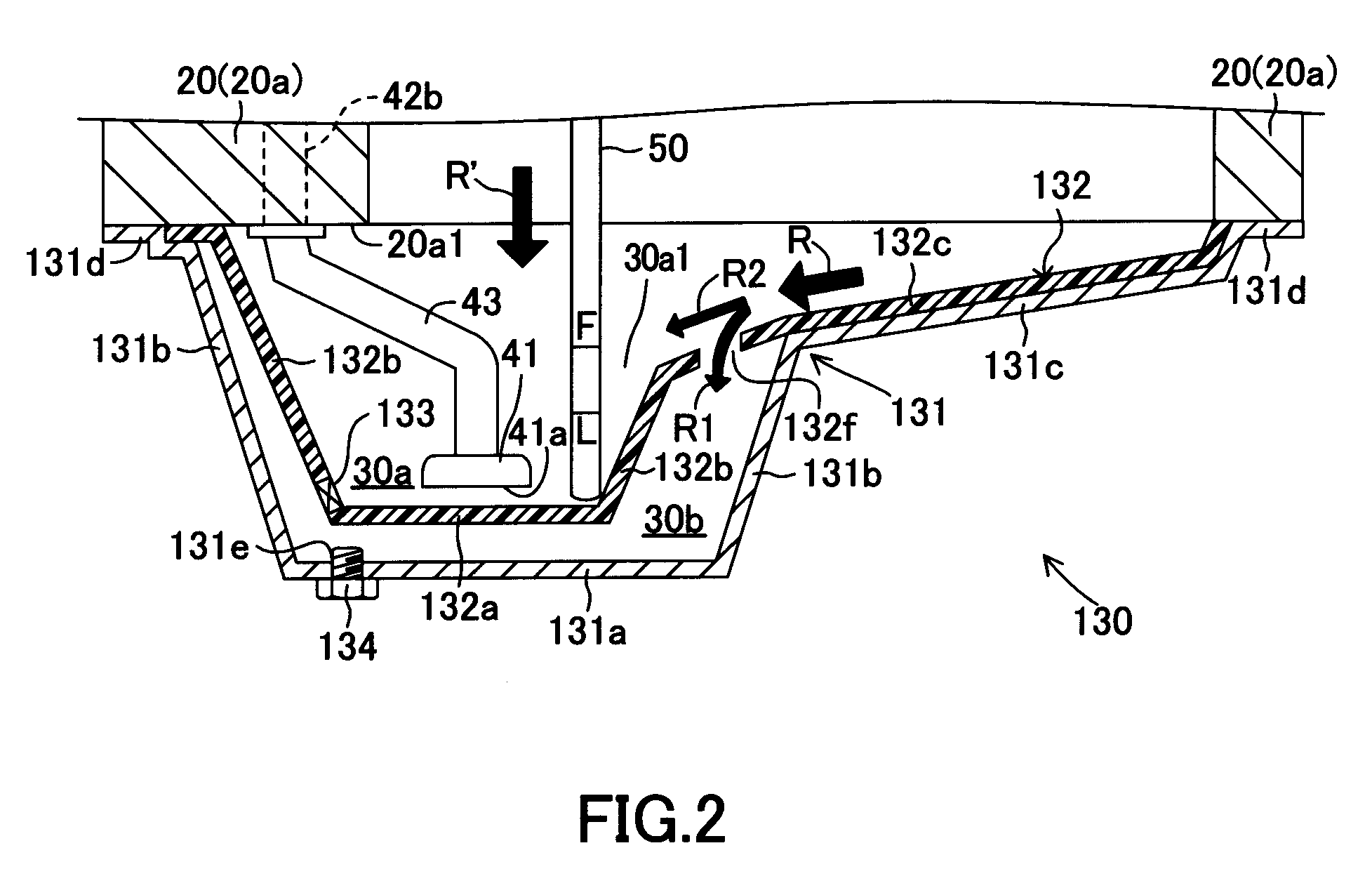
[0297]FIG. 9 is a lateral cross-sectional view illustrating the configuration of an oil pan 330 according to a sixth embodiment of the present invention that is included in the engine 10 shown in FIG. 1. The configuration of the sixth embodiment is virtually the same as that of the fifth embodiment. Almost all elements of the oil pan 630 according to the present embodiment are assigned the same reference numerals (same two lowest digits) as those of the oil pan 530 (see FIG. 8) according to the fifth embodiment. Therefore, the description of the fifth embodiment can be applied to various elements of the oil pan 630 according to the present embodiment.

[0298]However, the engine 10 according to the present embodiment is inclined at a predetermined angle to the vehicle as shown in FIG. 9. Therefore, when the vehicle is placed on level ground, the engine 10 is positioned at the predetermined angle to the horizontal.

[0299]The oil pan 630 according to the present embodiment is formed so th...


PUM


Abstract

An oil pan (130) comprises an oil pan cover (131) storing oil in an internal space and an oil pan separator (132) positioned in the internal space. The oil pan separator (132) is positioned so as to divide the internal space into a first chamber (30a), which has an oil strainer (41) at its bottom, and a second chamber (30b), which is adjacent to the first chamber (30a). The oil pan separator (132) includes a slope plate (132c) for capturing return oil that flows back from a cylinder block (20a) to an oil pan (130). Part of the captured return oil flows to the second chamber (30b) via a communication hole (132f) that is provided in the slope plate (132c). The remaining captured return oil flows into the first chamber (30a). This ensures that the oil level in the second chamber (30b) is higher than that in the first chamber (30a). Therefore, when a solenoid valve (133) opens at the end of a warm-up operation, the oil in the second chamber (30b) flows into the first chamber (30a).

Description

TECHNICAL FIELD[0001]The present invention relates to an oil pan that is capable of storing oil for lubricating a lubrication target mechanism (e.g., engine block or automatic transmission mechanism). The present invention also relates to a lubrication apparatus equipped with the oil pan (e.g., engine or automatic transmission).BACKGROUND ART[0002]In general, the lubrication apparatus of the above-mentioned type is configured so that the oil stored in the oil pan is taken in by an oil pump and supplied to lubrication target members (e.g., a gear, a camshaft, a cylinder, and a piston) in the lubrication target mechanism. Further, the lubrication apparatus is configured so that the oil lubricates the lubrication target members, absorbs friction-induced heat and other heat from the lubrication target members, and then flows back (returns) to the inside of the oil pan from the lubrication target mechanism due to gravity.[0003]A so-called two-tank oil pan structure is widely known as the...

Claims


Application Information

Patent Timeline
IPC IPC(8): F16N31/00
CPCF01M5/001F01M2011/0045F01M11/0004F01M5/00F01M11/00
Inventor MORI, TAIITHIMIZUTA, TAMETOSHIARISAWA, KATUHIKOYAMASHITA, YOSHIOKOBAYASHI, HIDEOYAMADA, KENICHIHAYASHI, KUNIHIKO
Owner TOYOTA JIDOSHA KK
Why Eureka
Try Eureka