Wind turbine tower and method for constructing a wind turbine tower

a wind turbine and wind power technology, applied in the field of wind power towers and wind power tower construction methods, can solve the problems of physical limits, and large tower section diameters, so as to reduce the total cost of production, avoid rolling, bending and/or welding, and minimize the total cost of large wind power towers

Active Publication Date: 2009-01-22
SIEMENS GAMESA RENEWABLE ENERGY AS
View PDF42 Cites 76 Cited by
  • Summary
  • Abstract
  • Description
  • Claims
  • Application Information

AI Technical Summary

Benefits of technology

[0025]The advantage of the present invention is that it minimises the total costs of large wind turbine towers by reducing the total costs of production, transportation and installation. Especially the use of flat plates, for instance, flat steel plates, avoids any rolling, bending and / or welding of the steel plates. Thereby, manufacturing costs are saved and the fatigue capability is improved. Further, flat plates allow the use of standard transportation equipment, for instance ordinary truck trailers, for transportation of the parts of the tower structure from the steel supplier to the installation site. The present invention makes it possible to assemble the components for the tower structure at the installation site in an efficient and simple way.
is that it minimises the total costs of large wind turbine towers by reducing the total costs of production, transportation and installation. Especially the use of flat plates, for instance, flat steel plates, avoids any rolling, bending and / or welding of the steel plates. Thereby, manufacturing costs are saved and the fatigue capability is improved. Further, flat plates allow the use of standard transportation equipment, for instance ordinary truck trailers, for transportation of the parts of the tower structure from the steel supplier to the installation site. The present invention makes it possible to assemble the components for the tower structure at the installation site in an efficient and simple way.

Problems solved by technology

This may cause difficulties concerning the transportation of a tower to the wind farm and the used infrastructure.
Larger wind turbine towers have typically lead to larger tower section diameters and longer and heavier tower sections.
The limiting aspects are typically physical limits such as free height under bridges and tunnels, allowable weights or the turning radii of roundabouts.
The increasing number of turbines in large wind projects has also caused difficulties since the equipment which is needed to transport the largest tower sections by road or by rail is highly specialised and is not found in the quantities necessary for the present number of transportations.
Consequently, when a large number of projects require a substantial amount of transportation time by road, the availability of special equipment may become difficult in the project phase.
For large turbines and tall towers this will typically lead to significantly higher weight.
This causes higher costs compared with when no diameter restrictions are applied.
However, above a certain practical height an extended foundation is expensive.
However, difficulties occur in the assembly and the complexity of the modular elements.

Method used


Image

  • Wind turbine tower and method for constructing a wind turbine tower
  • Wind turbine tower and method for constructing a wind turbine tower
  • Wind turbine tower and method for constructing a wind turbine tower

Examples


first embodiment

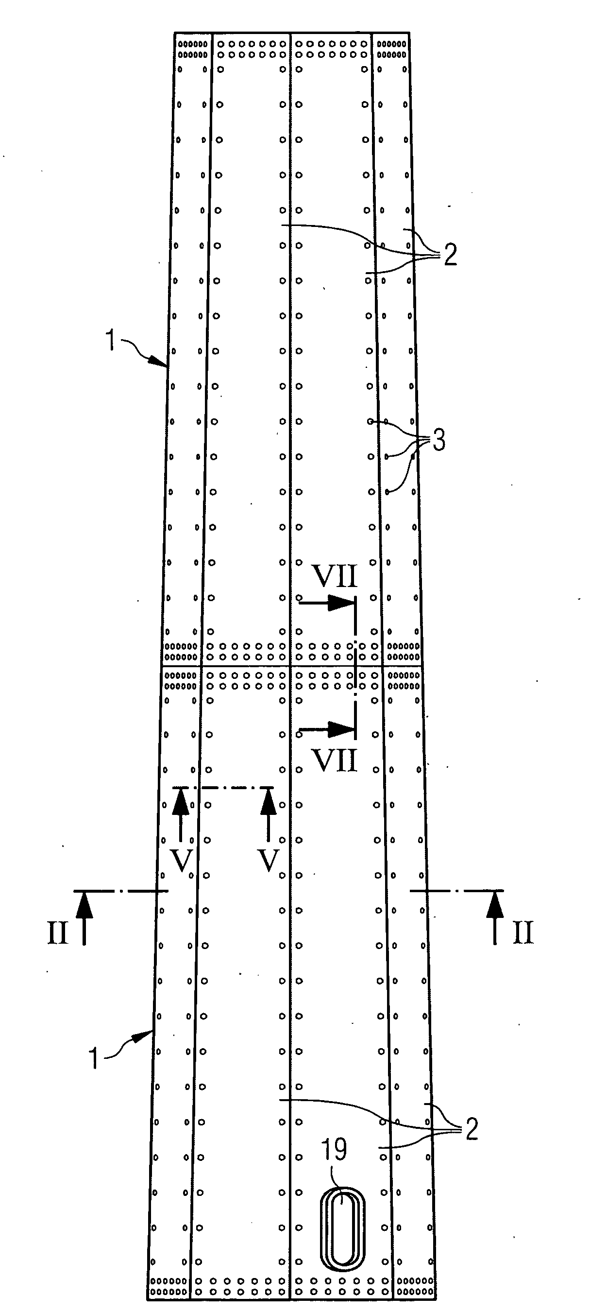
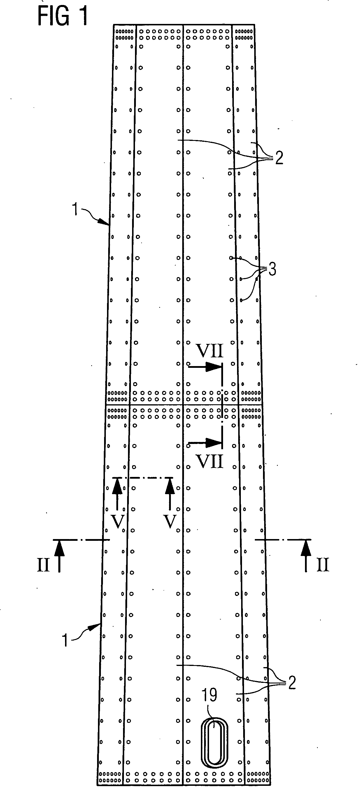
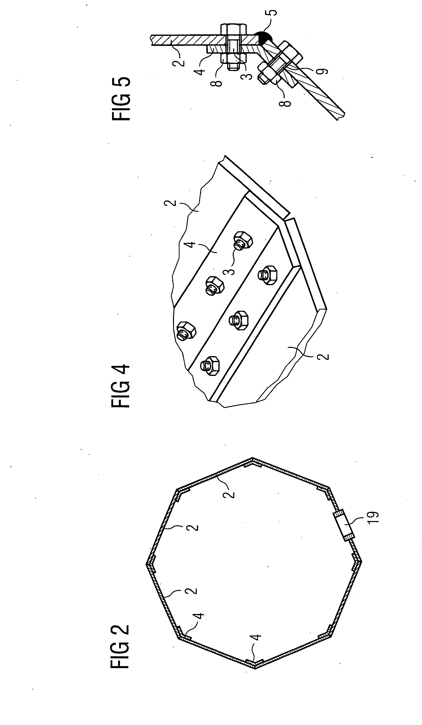
[0039]the inventive wind turbine tower will now be described with respect to FIGS. 1 to 7. FIG. 1 schematically shows part of an inventive wind turbine tower in a frontal view. The wind turbine tower comprises segments 1 which are connected to each other by means of bolts 3 and splice plates. The lowermost segment 1 includes a door 19, a manhole or the like to allow entering the interior of the tower after it is erected.

[0040]Each segment 1 comprises a number of flat plates 2. The flat plates 2 can have a trapezoid shape, as shown in FIG. 1 or, alternatively, a rectangular shape. They can be made of steel or rust resistant steel. Preferably the flat plates 2 have a width of 2.5 to 3 metres and a length of 10 to 14 metres. As an alternative to the flat shape of the flat plates 2 the flat plates 2 can also be corrugated plates. The flat plates 2 are also connected to each other by means of bolts 3 and splice plates. Instead of splice plates or bolts also flanges, nuts, bolt extensions...

third embodiment

[0053]In a third embodiment the inventive method for constructing a wind turbine tower will be described with respect to FIGS. 10 to 12. Elements corresponding to elements of the previous embodiments are designated with the same reference numerals and will not be described again to avoid repetition.

[0054]In FIG. 10 an assembly site is sketched which is close to the installation site of an inventive wind turbine tower. One can see in FIG. 10 rails 16 with transport carts 15, a crane 13, a plate storage 14, carriages 10 and a rotation tool 11. At first the delivered flat plates 2 are transported to the installation site by transport carts 15 which is sketched on the right side of FIG. 10. Then the flat plates 2 may be lifted from the transport cart 15 by a crane 13 and stored in a plate storage 14. Instead of a crane 13 any other lifting device may be used, for example a magnet or a vacuum lifting device.

[0055]For assembling a segment 1 the flat plates 2 can be transported by means of...


PUM


Abstract

A wind turbine tower is provided, which comprises a number of segments with a polygonal cross section, each segment comprising a number of flat plates which are connected to each other so as to form the polygonal cross section. Further, a method for constructing a wind turbine tower which comprises segments assembled of flat plates is disclosed, wherein the flat plates are connected to each other so as to form segments with a polygonal cross section and the segments are connected to each other so as to form the tower.

Description

CROSS REFERENCE TO RELATED APPLICATIONS[0001]This application claims the benefits of European application No. 07012103.3 filed Jun. 20, 2007, and is incorporated by reference herein in its entirety.FIELD OF INVENTION[0002]The present invention relates to a wind turbine tower and a method for constructing a wind turbine tower.BACKGROUND OF THE INVENTION[0003]Wind turbine towers, especially tubular steel towers for large wind turbines, are large in diameter and weight. This may cause difficulties concerning the transportation of a tower to the wind farm and the used infrastructure. Usually, the steel towers for wind turbines are produced as sections in shops and the sections are then transported to the place of installation. The towers are typically constructed of a number of sections which have a cylindrical or conical shape.[0004]In the wind industry the requirements for larger turbines have resulted in corresponding requirements for larger wind turbine towers. Larger wind turbine t...

Claims


Application Information

Patent Timeline
Patent Type & Authority Applications(United States)
IPC IPC(8): F03D9/00E04H12/00
CPCE04H12/085F03D11/04Y02E10/728F05B2240/912F05B2230/00F03D13/20E02B2017/0078Y02P70/50Y02E10/72
Inventor THOMSEN, JENS
Owner SIEMENS GAMESA RENEWABLE ENERGY AS
Why Eureka
Try Eureka