Pwm controller with output current limitation

a controller and output current technology, applied in the direction of process and machine control, pulse technique, instruments, etc., can solve the problem of increasing the and achieve the effect of reducing the circuit cost of the power supply and simplifying the layout of the pcb

Inactive Publication Date: 2009-01-22
NIKO SEMICON
View PDF4 Cites 56 Cited by
  • Summary
  • Abstract
  • Description
  • Claims
  • Application Information

AI Technical Summary

Benefits of technology

[0009]One particular aspect of the present invention is to provide a PWM controller with output current limitation. Its over-current limitations are almost the same even though the input voltages are dif

Problems solved by technology

Therefore, the current specification of devices, such as the transformer T1, the output diode D2

Method used


Image

  • Pwm controller with output current limitation
  • Pwm controller with output current limitation
  • Pwm controller with output current limitation

Examples


Embodiment Construction

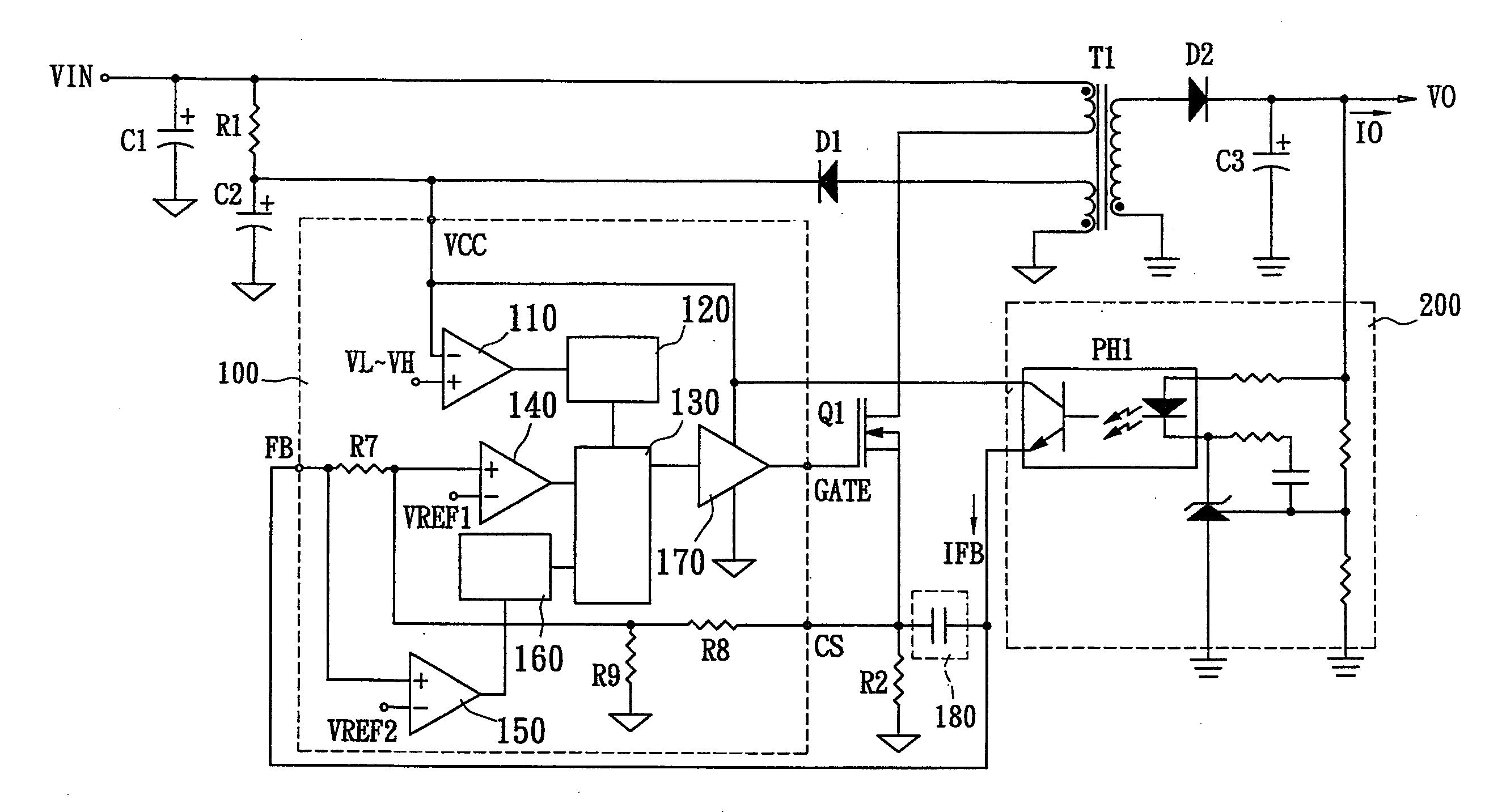
[0021]The present invention utilizes the characteristic of the levels of the current detecting signals on the primary side of the transformer being different when the input voltages are different. It couples the current detecting signal to the feedback signal of the detecting circuit at the output terminal to compensate for the feedback signal. Thereby, the output current limitations for different input voltages are almost the same.

[0022]FIG. 3 shows a schematic diagram of the switch power supply of the present invention. The switch power supply includes a controller 100, a power switch Q1, a current detector R2, a transformer T1, an output detector 200, and a compensating device C5. The current detector R2 detects the current flowing through the primary side of the transformer T1 and generates a current detecting signal to the current detecting signal terminal CS of the controller 100. The output detector 200 detects the voltage of the primary side of the transformer T1 and generat...


PUM


Abstract

A PWM controller with output current limitation makes the over-current limitations almost the same even though the input voltages are different. The designer does not need to use high specification components or add an output current limiting circuit against the over-current condition. Costs are reduced and the layout is simplified. The switch power supply includes a transformer, a power switch, a first detecting circuit for generating a first detecting signal, a second detecting circuit for generating a second detecting signal, and a controller. The transformer converts the power and outputs the power to the secondary side. The power switch has a first terminal, a second terminal, and a controlled terminal. The controller has a control terminal, a first detecting terminal for receiving the first detecting signal, and a second detecting terminal for receiving the second detecting signal. The controller performs a protecting operation according to the received signals.

Description

BACKGROUND OF THE INVENTION[0001]1. Field of the Invention[0002]The present invention relates to a PWM controller with output current limitation. Its over-current limitations are almost the same even though the input voltages are different. The cost of the power supply circuit is reduced and the layout of the PCB is simplified.[0003]2. Description of the Related Art[0004]FIG. 1 shows a flyback power supply. When the power is turned on, the input power VIN provides a small current to charge the capacitor C2 via the resistor R1. When the voltage of the capacitor C2 reaches the operating voltage VH (this means that the voltage of VCC pin reaches the operating voltage VH), the UVLO (Undervoltage Lockout) comparator outputs a low level signal to release the oscillating circuit 20. At this time, the oscillating circuit 20 outputs a pulse signal to the input terminal S of the SR flip-flop 25. After the SR flip-flop 25 receives the pulse signal from the oscillating circuit 20, it outputs a ...

Claims


Application Information

Patent Timeline
IPC IPC(8): G05F1/10
CPCH02M3/33523H02M1/32
Inventor HSU, TA-CHING
Owner NIKO SEMICON
Why Eureka
Try Eureka