
Capacitive detection of dust accumulation in a heat sink

a heat sink and capacitive technology, applied in the direction of resistance/reactance/impedence, instruments, material analysis, etc., can solve the problems of increasing the amount and rate of dust deposited, the airflow used to cool the computer carries some amount of dust, and the problem of problems in the computer system

Inactive Publication Date: 2009-01-22
IBM CORP
View PDF11 Cites 30 Cited by
  • Summary
  • Abstract
  • Description
  • Claims
  • Application Information

AI Technical Summary

Problems solved by technology

Despite efforts to keep a computer center clean and filter dust out of the air, the airflow used to cool a computer carries some amount of dust, which accumulates over time on internal components of the computer.
The electrostatic charge generated by some components tends to attract dust, increasing the amount and rate of dust deposited.
Unfortunately, dust accumulation can cause problems in a computer system.
Excessive dust build-up can reduce performance, increase the rate at which components fail, and reduce overall system reliability.
Dust can interfere with operation of moving parts, such as fan blades and mechanical connectors, and reduce the reliability of electrical components, such as by dirtying electrical contacts in electrical connectors.
Dust can even give off an unpleasant odor in the presence of hot components.
Dust can be especially problematic for heatsinks.
Thus, dust may accumulate more heavily on a heatsink than on other components.
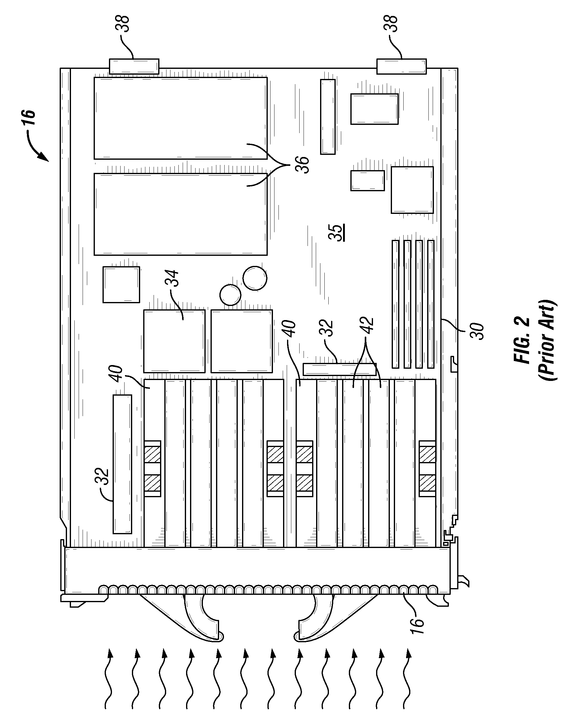
Dust deposited on heatsink fins can reduce the thermal efficiency of the heatsink, which affects the temperature and cooling performance of the hardware device in contact with the heatsink.
Furthermore, the need to remove and inspect each server and other hardware devices for accumulated dust causes an increase in the time and associated expense involved with system maintenance.
It may not be readily apparent when enough dust has accumulated within a hardware device to require servicing the hardware device.
Manually inspecting hardware for dust is inefficient, usually necessitating the removal of the hardware from the chassis.

Method used


Image

  • Capacitive detection of dust accumulation in a heat sink
  • Capacitive detection of dust accumulation in a heat sink
  • Capacitive detection of dust accumulation in a heat sink

Examples


Embodiment Construction

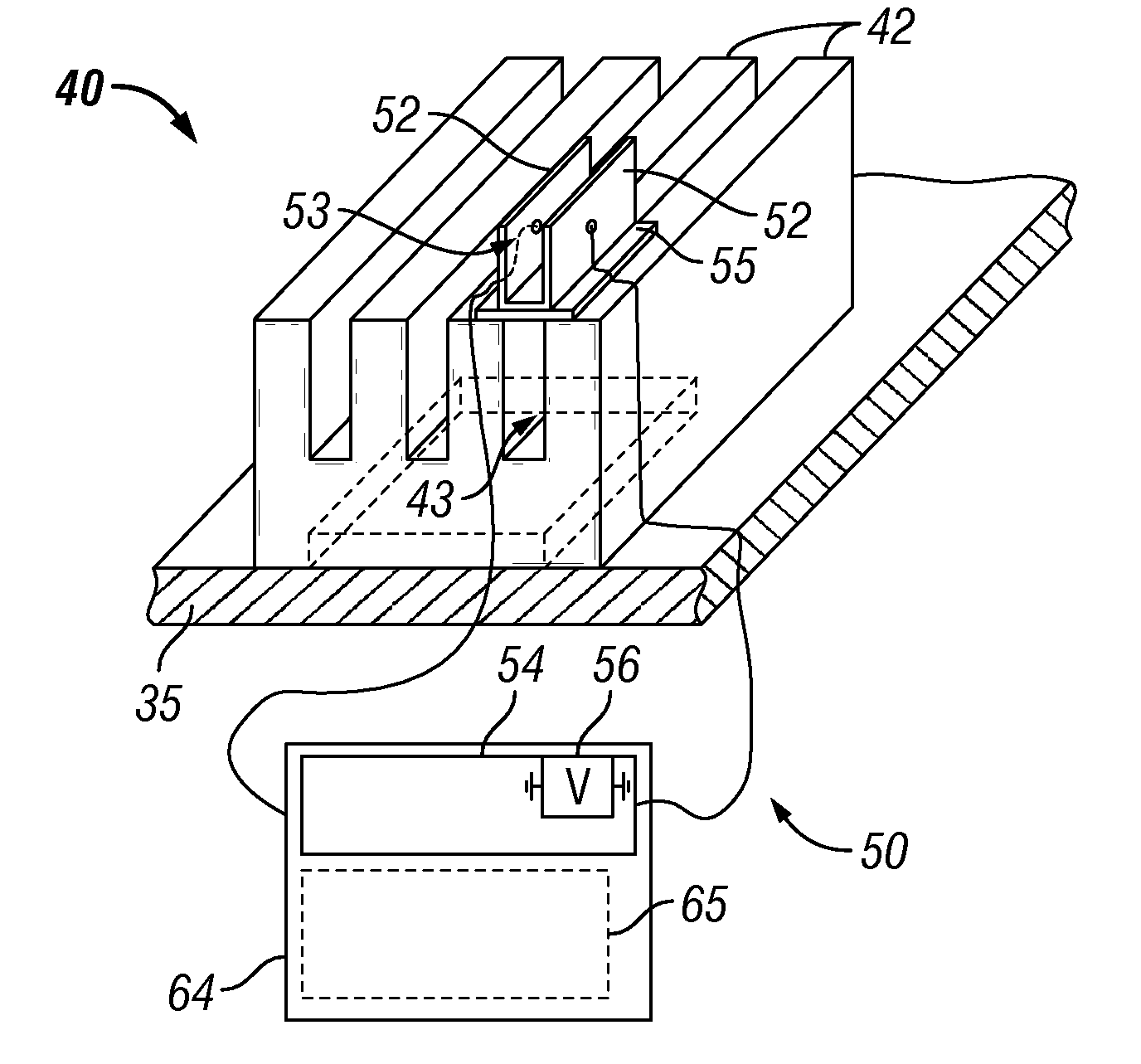
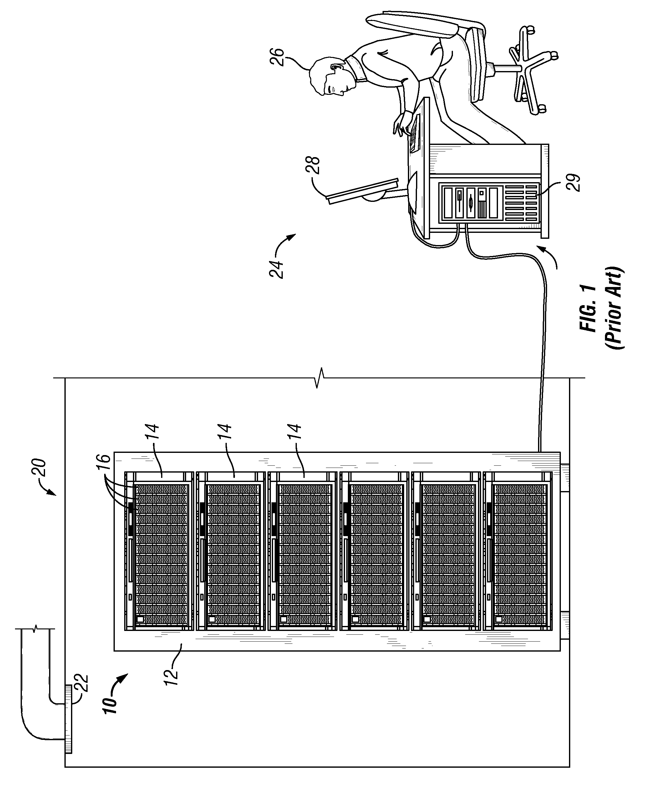
[0020]The present invention provides a system and method for electronically detecting the presence of dust within a computer system using a capacitive sensor responsive to the accumulation of dust. The dust detection system may be implemented in a smaller computer, such as an individual PC, or in a more expansive system, such as a rack-based server system (“rack system”) having multiple blade servers and other hardware devices. In one embodiment, each blade server in a rack system detects the internal accumulation of dust within the blade server and generates an alert when the accumulation of dust has reached a certain level. The alerts may be received by a management console for the attention of a system administrator. Each alert may contain the identity of the blade server generating the alert, so that the system administrator knows which blade server(s) need to be cleaned. Identifying blade servers or other components that have an accumulation of dust results in tremendous saving...


PUM


Abstract

A system and method for electronically detecting the accumulation of dust within a computer system using a capacitive dust sensor. The dust detection system may be implemented on a smaller computer, such as an individual PC, or in a more expansive system, such as a rack-based server system (“rack system”) having multiple servers and other hardware devices. In one embodiment, each server in a rack system includes a capacitive sensor responsive to the accumulation of dust. The capacitive sensor may include one or more capacitive plates integral with a heatsink. As dust collects on the capacitive plates, the capacitance increases. When a capacitance setpoint is reached, indicating the dust has reached a critical level, an alert is generated. The alerts may be received by a management console for the attention of a system administrator. Each alert may contain the identity of the server generating the alert, so that the system administrator knows which server(s) are to be removed for cleaning.

Description

BACKGROUND OF THE INVENTION[0001]1. Field of the Invention[0002]The present invention relates to the detection and removal of dust in electronic systems.[0003]2. Description of the Related Art[0004]Airflow is commonly used to remove heat generated by components within a computer. For example, an individual PC typically includes one or more on-board cooling fans disposed within the housing to cool the processors, power supply, memory, and other internal components. In more expansive computer systems, such as rack-based computer systems having multiple servers, one or more blower modules are supported on a chassis along with the servers to generate airflow through the servers and other components. Despite efforts to keep a computer center clean and filter dust out of the air, the airflow used to cool a computer carries some amount of dust, which accumulates over time on internal components of the computer. The electrostatic charge generated by some components tends to attract dust, in...

Claims


Application Information

Patent Timeline
IPC IPC(8): G01R27/26
CPCG01N27/223H01L23/34H01L2924/0002H01L2924/00
Inventor BANDHOLZ, JUSTIN POTOKDURHAM, ZACHARY BENSONKERR, CLIFTON EHRICHMAXWELL, JOSEPH ERICREINBERG, KEVIN MICHAELVERNON, KEVIN S.WEINSTEIN, PHILIP LOUISWEST, CHRISTOPHER COLLIER
Owner IBM CORP
Learn More