Optical element positioning apparatus, projection optical system and exposure apparatus

a positioning apparatus and optical element technology, applied in the field of optical element positioning apparatus, can solve the problems of measurement errors, limited lithography using ultraviolet light, and difficult to measure the position and posture of the optical elements disposed within the optical element holding barrel of the projection optical system,

Inactive Publication Date: 2009-01-22
CANON KK
View PDF6 Cites 18 Cited by
  • Summary
  • Abstract
  • Description
  • Claims
  • Application Information

AI Technical Summary

Problems solved by technology

However, since the miniaturization of semiconductor devices progresses rapidly, there is a limit in the lithography using the ultraviolet light.
However, due to the actual disposition of the laser gauge interferometers, it is extremely difficult to measure the position and posture of the optical elements disposed within an optical element holding barrel of the projection optical system, from such a measuring frame.
When the laser gauge interferometers are mounted on the optical element holding barrel as disclosed in Japanese Patent Laid-Open No. 2005-175177, mounting errors of the laser gauge interferometers cause Abbe errors, which cause errors in measurement results of the movement amounts of the mirrors.
However, it is extremely difficult to precisely obtain the positions of the laser gauge interferometers mounted on the optical element holding barrel and the spans therebetween.
Even when the measuring apparatus in which the first and second sensors whose measurement axes are previously adjusted in the first and second axial directions is used as disclosed in Japanese Patent Laid-Open No. 2006-250587, a measurement error caused from the mounting error of the measuring apparatus cannot be prevented.

Method used


Image

  • Optical element positioning apparatus, projection optical system and exposure apparatus
  • Optical element positioning apparatus, projection optical system and exposure apparatus
  • Optical element positioning apparatus, projection optical system and exposure apparatus

Examples


embodiment 1

[0030]While taking an EUV exposure apparatus as an example, an optical element positioning apparatus and a projection optical system mounted therewith, each of which is a first embodiment (Embodiment 1) of the present invention, will be described below.

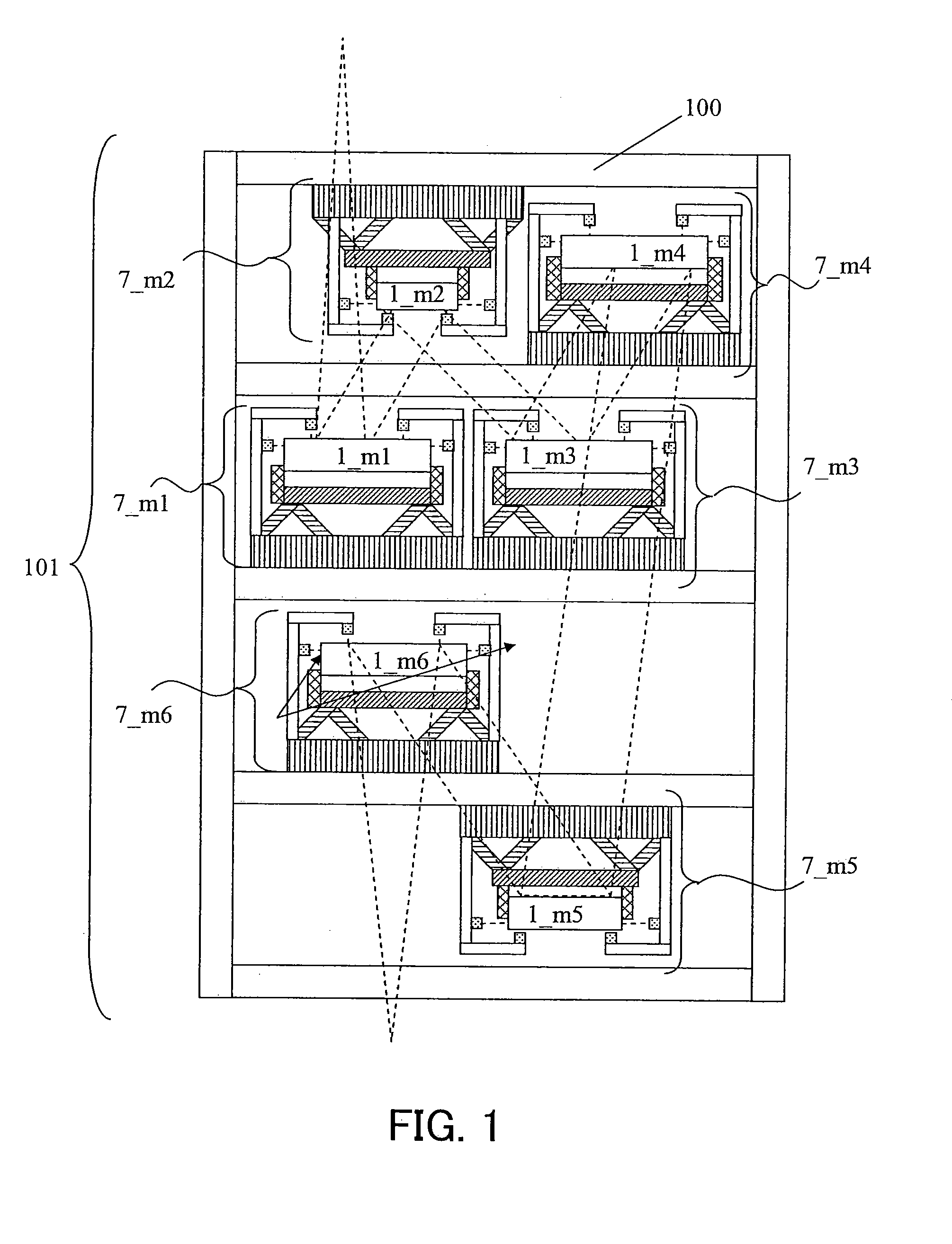
[0031]In many cases, a projection optical system that mounted on an EUV exposure apparatus is constituted by six or eight optical elements (mirrors). In Embodiment 1, description will be made of a projection optical system which includes an optical element holding barrel containing six optical elements 1 (1_m1 to 1_m6) as shown in FIG. 1.

[0032]The optical elements 1 (1_m1 to 1_m6) are respectively mounted on optical element positioning apparatuses 7 (7_m1 to 7_m6). A projection optical system 101 is constituted by mounting the optical element positioning apparatuses 7 on an optical element holding barrel 100.

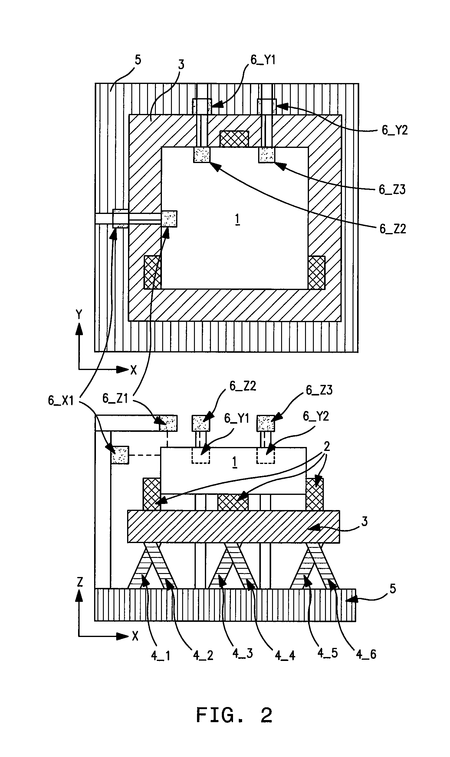
[0033]FIG. 2 illustrates the configuration of one of the optical element positioning apparatuses 7. The optical element position...

embodiment 2

[0086]The optical element positioning apparatus 7 described in Embodiment 1 uses the displacement sensors 6 mounted on the base plate 5 to measure the positions of the optical element 1 with respect to the base plate.

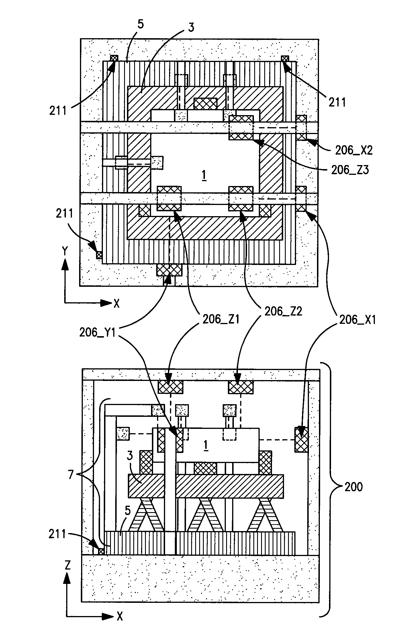
[0087]However, when the rigidity of the holding mechanism 2 is satisfactorily high and thereby the optical element 1 and the back plate 3 can be regarded as they are integrally moved, as shown in FIG. 5, the displacement sensors 6 (6_X1, 6_Y1, 6_Y2, 6_Z1, 6_Z2, 6_Z3) may be mounted to the base plate 5 to measure the displacement amounts of three points different from each other on the back plate 3 in the Z axial direction, the X axial direction and the Y axial direction.

[0088]In this case, the positioning control of the optical element 1 may be carried out in the same manner as that in Embodiment 1, based on the measurement results of the position of the back plate 3 with respect to the base plate 5.

embodiment 3

[0089]Next, an example of a projection exposure apparatus 300 in which a projection optical system shown in aforementioned Embodiments 1 and 2 is provided will be described with reference to FIG. 12.

[0090]The exposure apparatus 300 of this embodiment uses EUV light as illumination light, for example its wavelength is 13.5 nm, to expose onto a substrate 340 as a wafer a circuit pattern formed on an exposing mask 320 by a step-and-scan method, a step-and-repeat method or the like. This exposure apparatus 300 is suitable for lithography processing in a size of smaller than submicron or quarter micron. Hereinafter, this embodiment will describe an exposure apparatus by the step-and-scan method, which is also referred to as a scanner, as an example.

[0091]The step-and-scan method is an exposure method in which continuous scanning of a wafer with respect to an exposing mask is performed to expose a pattern formed on the exposing mask onto the wafer, and the wafer is moved to a next exposur...


PUM


Abstract

The apparatus includes a holder holding an optical element, a back plate supporting the optical element via the holder, a mechanism moving the optical element in a six-degree-of-freedom, a base plate supporting the back plate via the mechanism, and six displacement sensors disposed on the base plate and measuring displacement amounts of different points on the optical element. The displacement sensors includes three ones measuring them in a first direction, one measuring it in a second direction, and two ones measuring them in a third direction. The apparatus further includes a transformation processor transforming the six measured displacement amounts into displacement amounts of the optical element in the six-degree-of-freedom, a calibration processor calibrating the transformed displacement amounts, and a controller outputting command values to the displacing mechanism based on differences between the calibrated displacement amounts and target displacement amounts of the optical element.

Description

BACKGROUND OF THE INVENTION[0001]The present invention relates to an optical element positioning apparatus that performs positioning of an optical element suitable for, for example, an exposure apparatus used in a lithography process of a device manufacturing process.[0002]Semiconductor devices such as semiconductor memories and logical circuits with a minute circuit pattern are manufactured using a photolithography (exposure) technique. For this purpose, conventionally, a reduction projection exposure apparatus is used. The reduction projection exposure apparatus projects a circuit pattern drawn on a reticle (or mask) through a projection optical system onto a substrate like a wafer to transfer the circuit pattern thereon.[0003]A minimum dimension (resolution) transferable with the reduction projection exposure apparatus is proportional to a wavelength of light used for exposure, and inversely proportional to a numerical aperture (NA) of the projection optical system. Accordingly, ...

Claims


Application Information

Patent Timeline
Patent Type & Authority Applications(United States)
IPC IPC(8): G02B7/00
CPCG02B7/005G03F7/70825G03F7/70258G02B7/1827
Inventor NAWATA, RYOMIZUNO, MAKOTOUZAWA, SHIGEYUKI
Owner CANON KK
Why Eureka
Try Eureka