Pitch Bearing For A Wind Turbine, A Wind Turbine And A Method For Servicing A Bearing

a technology for pitch bearings and wind turbines, which is applied in the direction of bearings, roller bearings, shafts, etc., can solve the problems of deterioration of bearings and lack of capacity of ball bearings to handle the increase in load, so as to improve service life, reduce costs, and facilitate service.

Inactive Publication Date: 2009-01-22
VESTAS WIND SYST AS
View PDF7 Cites 17 Cited by
  • Summary
  • Abstract
  • Description
  • Claims
  • Application Information

AI Technical Summary

Benefits of technology

[0010]In an aspect of the invention, said one or more radial rows of bearing elements are positioned on the upper side of the bearing above the first and second axial row e.g. close to the blade side of the pitch bearing or said one or more radial rows of bearing elements are positioned on the lower side of the bearing below the first and second axial row e.g. close to the hub side of the pitch bearing. If the radial row is relocated from in between the two axial races to the upper of the b...

Problems solved by technology

However, by the increasing size of the modern wind turbine, the ball bearing lacks capacity to handle the ...

Method used


Image

  • Pitch Bearing For A Wind Turbine, A Wind Turbine And A Method For Servicing A Bearing
  • Pitch Bearing For A Wind Turbine, A Wind Turbine And A Method For Servicing A Bearing
  • Pitch Bearing For A Wind Turbine, A Wind Turbine And A Method For Servicing A Bearing

Examples


first embodiment

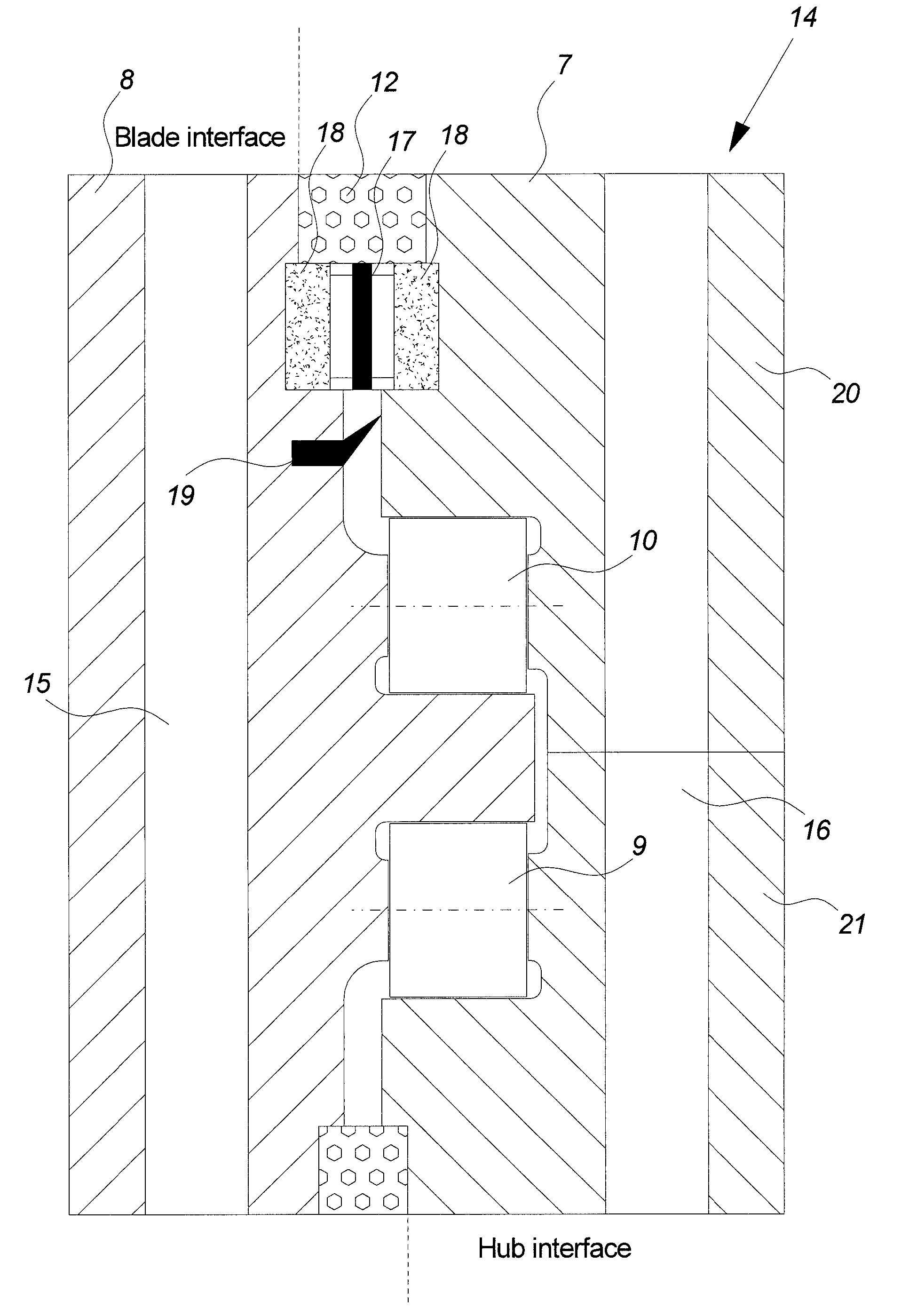
[0035]FIG. 3a illustrates a cross sectional view of a bearing according to the invention.

[0036]The bearing 14 comprises an outer and inner bearing ring 7, 8 comprising sets of raceways.

[0037]Two horizontal sets of raceways hold two axial rows 9, 10 of rolling elements such as rollers. The two axial rows 9, 10 are separated by a horizontal extension part of the inner bearing ring 8 holding some of the horizontal raceways. Similarly the outer ring comprises an upper and lower extension part holding the further horizontal raceways for the two axial rows.

[0038]The radial row 17, 18 of bearing elements is positioned above the two axial rows 9, 10 at the blade side of the bearing 14. The radial row comprises some kind of rolling element 17 and corresponding raceways 18 in opposite side of the inner and outer ring 7, 8. The raceways are illustrated as extending into the inner and outer ring and as such keeping the raceways vertically in place during normal use. The bearing rolling elements...

second embodiment

[0058]FIG. 4 illustrates an upper part of a bearing according to the invention wherein the radial row is established with chambered rollers.

third embodiment

[0059]FIG. 5 illustrates an upper part of a bearing according to the invention.

[0060]The radial row is established with a ball bearing with raceways shaped to guide the balls. A low conformity between the balls and the raceways may be preferred in order to allow axial movement within the radial ball bearing. The lower conformity may be obtained by oval shaped raceways or larger diameter on the relevant parts of the raceways in relation to the ball diameter.

[0061]Spring holding means 29 is positioned in a notch of the outer ring in order to retain the ball bearing in place during normal use. The notch is positioned in between the sealing means 12 and the ball bearing.

[0062]The spring holding means 29 may also be positioned in a notch of the inner ring or in notches of both the outer and inner ring.

[0063]The sealing means 12 are illustrated as having the width as the ball bearing including the raceways. Hereby it is possible to lift out the ball bearing as a whole after the spring hol...


PUM


Abstract

The invention relates to a pitch bearing for a wind turbine comprising a first and second axial row of bearing rolling elements, said rows being positioned in a distance of each other, and one or more radial rows of bearing elements, where said one or more rows of bearing elements are positioned outside an area defined in between said first and second axial row. The invention also relates to a wind turbine and method for servicing a bearing hereof.

Description

CROSS-REFERENCE TO RELATED APPLICATIONS[0001]The present application is a continuation of pending International patent application PCT / DK2007 / 000162, filed Mar. 30, 2007, which designates the United States and claims priority from Danish patent application no. PA 2006 00469, filed Apr. 2, 2006, the content of which is incorporated herein by reference.FIELD OF THE INVENTION[0002]The present invention relates to a pitch bearing for a wind turbine, a wind turbine and a method for servicing a bearing.BACKGROUND OF THE INVENTION[0003]A typical bearing in a wind turbine has been the 4-point contact ball bearing e.g. in a blade pitch mechanism. This bearing design has shown its suitability to take the complexes load patterns the blade act on the bearing with.[0004]As the blade rotates in the gravity field, the wind related loads are super positioned by gravity related loads. These gravity loads are cyclic and change directions during the rotation of the rotor. This causes the loads in some...

Claims


Application Information

Patent Timeline
IPC IPC(8): F16C19/49
CPCF03D7/0224F03D11/0008F05B2230/80F05B2260/79F16C19/30Y02E10/723F16C19/54F16C21/00F16C33/76F16C2300/14Y02E10/722F16C19/381F16C2360/31F03D80/70Y02E10/72Y02P70/50
Inventor BECH, ANTONMADDEN, GERRY
Owner VESTAS WIND SYST AS
Why Eureka
Try Eureka