Perforator with inner and outer drills and a drive head, the inner drill configured to move against the outer drill in order to disengage from the drive head

a perforator and drive head technology, applied in the field of medical perforators, can solve the problems of clogging the inner drill, exposing the underlying dura to shavings, and the resultant pilot bore is known to be filled with bone shavings, and achieve the effect of reducing the exten

Inactive Publication Date: 2009-01-22
STRYKER EURO OPERATIONS HLDG LLC
View PDF10 Cites 53 Cited by
  • Summary
  • Abstract
  • Description
  • Claims
  • Application Information

AI Technical Summary

Benefits of technology

[0010]This invention is directed to a new and useful perforator for forming a bore in bone. The perforator of this invention is especially useful for forming a bore in the skull. The perforator of this invention is designed so as that its inner and outer drills stop rotating very shortly after the inner drill penetrates the bone in which the bore is being formed. The perforator of this invention is further designed to minimize the extent to which bone chips accumulate in the pilot bore formed by actuation of the perforator.
[0013]The perforator of this invention is also provided with an inner drill with features that minimize the extent to which the inner drill, upon reinsertion into a partially formed bore, penetrates the bone at the base of the bore. This feature as well as the geometry of how the inner drill engages the drive head, increases the likelihood that when the perforator is reinserted in the bore, the drive head will engage and actuate the inner drill so as to rotate the latter component.

Problems solved by technology

The displacement of the drills of certain of these perforators is known to potentially expose the underlying dura to injury.
However, when a perforator is provided with a leading pyramid, the resultant pilot bore is known to fill with bone shavings.
These shavings clog the inner drill.
The heat generated by these shavings can potentially damage surrounding tissue that would otherwise not be affected by the bore drilling process.
Some known perforators do not easily reset once their drills have so disengaged.
Once removed from a partially formed bore, this type of perforator may be difficult to reset and restart in order to complete the formation of the bore.

Method used


Image

  • Perforator with inner and outer drills and a drive head, the inner drill configured to move against the outer drill in order to disengage from the drive head
  • Perforator with inner and outer drills and a drive head, the inner drill configured to move against the outer drill in order to disengage from the drive head
  • Perforator with inner and outer drills and a drive head, the inner drill configured to move against the outer drill in order to disengage from the drive head

Examples


Embodiment Construction

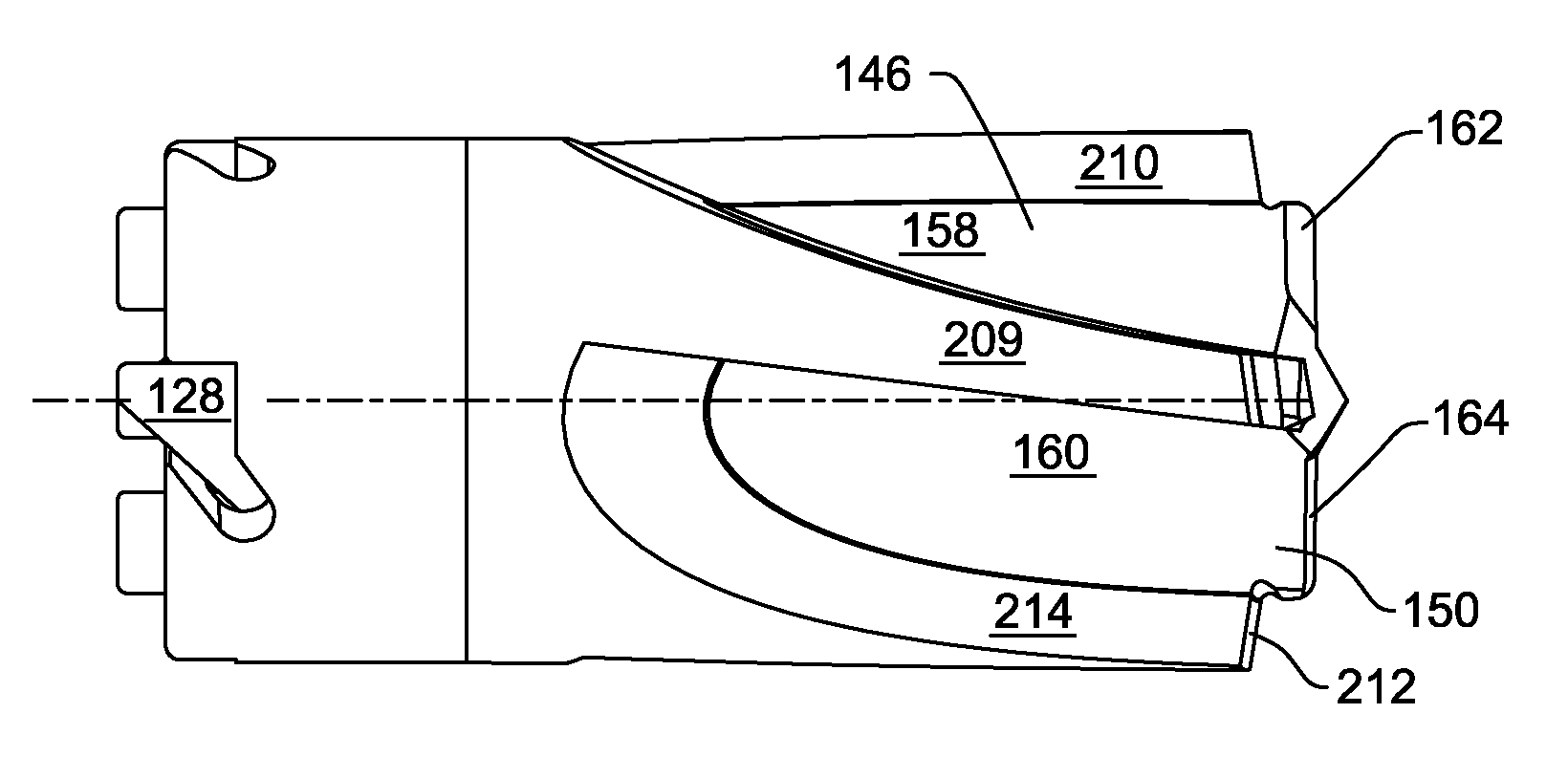
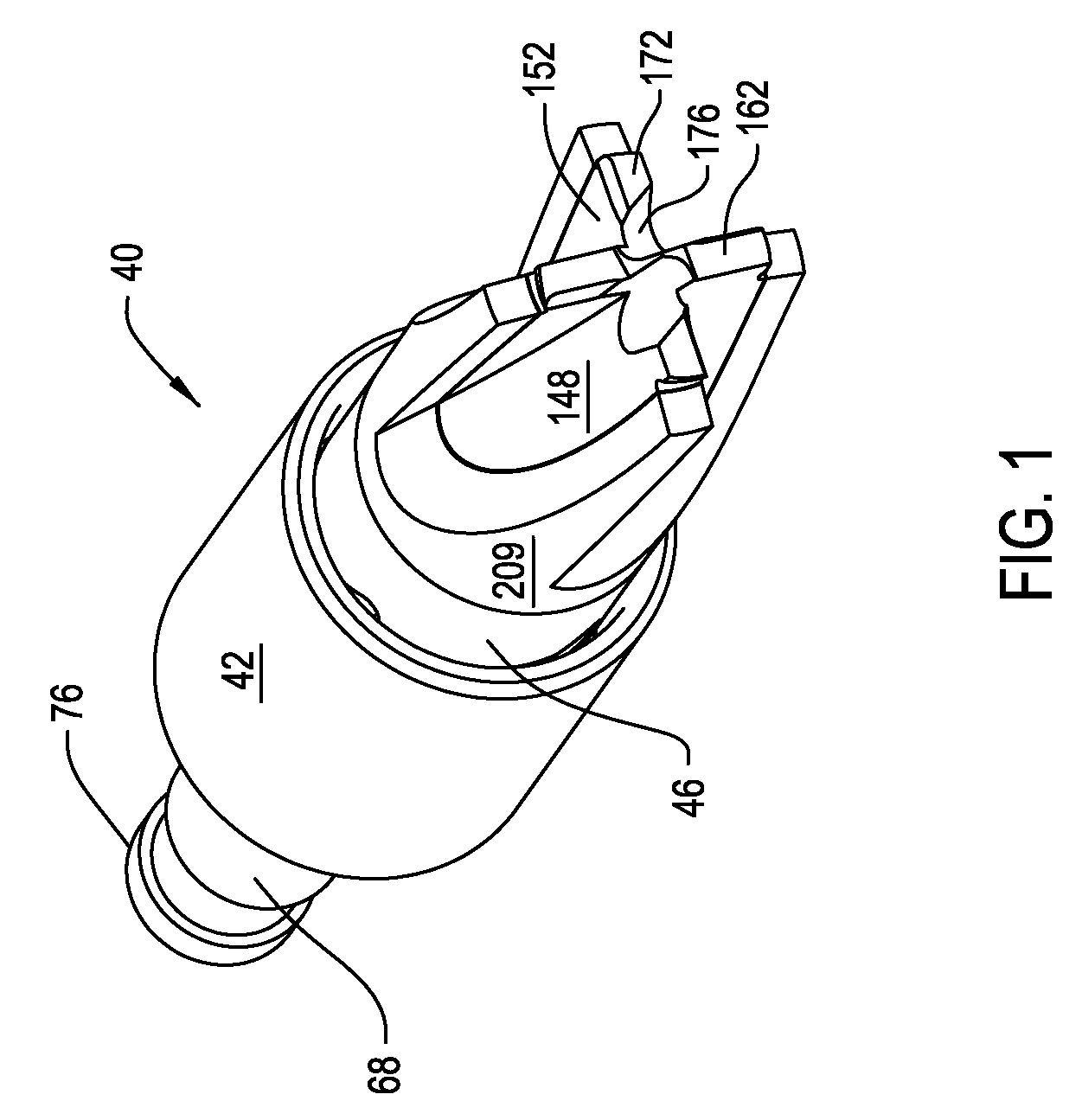
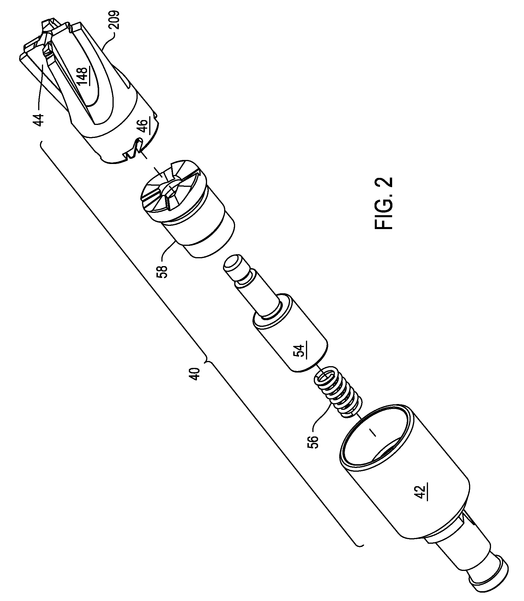
[0036]FIGS. 1 and 2 illustrate a perforator 40 constructed in accordance with this invention. Perforator 40 includes a drive head, head 42, from which inner and outer drills 44 and 46, respectively, extend. Inner drill 44 is generally cylindrically shaped. Outer drill 46 is generally tube shaped and disposed over inner drill 44. As discussed in detail below, the inner drill 44 is formed with cutting flutes 146-152. Outer drill 46 is formed with cutting flutes 209.

[0037]A plunger 54 disposed inside the head 42 is connected to the inner drill 44. A spring 56, also disposed inside the head 42 abuts the plunger 54. Spring 56 urges the plunger 54 and, by extension, the inner and drill 44 distally forward. (“Distal” is understood to be away from the clinician holding the perforator 40, towards the patient. “Proximal” is understood to mean towards the clinician, away from the patient.) A drive cap 58 is disposed over the distal end of the head 42. Drive cap 58 limits the extent to which th...


PUM

PropertyMeasurementUnit
longitudinal displacementaaaaaaaaaa
angleaaaaaaaaaa
angleaaaaaaaaaa

Abstract

A cranial perforator with an inner drill and an outer drill that surrounds the inner drill. Both drills are rotated by a head. Once the inner drill penetrates the bone, the inner drill moves against the outer drill. This movement causes the inner drill to disengage from the perforator head. The disengagement of the inner drill from the perforator head serves to stop the rotation of both drills.

Description

FIELD OF THE INVENTION[0001]This invention is generally related to a medical perforator such as a cranial perforator. More particularly, this invention is related to a medical perforator with inner and outer drills, wherein the inner drill moves against the outer drill to cause both drills to disengage from the drive head.BACKGROUND OF THE INVENTION[0002]A perforator is a medical device designed to cut through tissue. One such perforator is a cranial perforator. In a neurological surgical procedure, the cranial perforator is used to form the initial access bore into the skull. Depending on the type of procedure, once this initial hole is formed another instrument, a craniotom, is used to cut the skill so that a large portion of the skull can be removed. In some procedures, the bore formed by the perforator provides sufficient access to the underlying tissue on which the remainder of the procedure is to be performed.[0003]During the process of forming the bore in the skull, care must...

Claims


Application Information

Patent Timeline
Patent Type & Authority Applications(United States)
IPC IPC(8): A61B17/16
CPCA61B17/1617A61B17/1695Y10T408/9065A61B2019/305A61B2019/303A61B2090/033A61B2090/035
Inventor GORDON, JEREMYMANLEY, KEVINGORDON, HEATHER
Owner STRYKER EURO OPERATIONS HLDG LLC
Why Eureka
Try Eureka