
Implant plate screw locking system and screw having a locking member

a technology of locking system and screw, which is applied in the field of implant plate system, device and locking screw, can solve the problems of increasing the possibility of user error or false fixation, insufficient fixation of implant device, and loosening of implant device and associated bone graft, and achieve the effect of facilitating preventing screw migration

Active Publication Date: 2009-01-22
X SPINE SYST
View PDF99 Cites 67 Cited by
  • Summary
  • Abstract
  • Description
  • Claims
  • Application Information

AI Technical Summary

Benefits of technology

"The patent text describes a plate system with a screw and a plate that have a pawl to prevent the screw from moving. This improves the locking system of the plate system. The technical effect of this invention is to enhance the stability and security of the plate system, ensuring that the screw remains in place and can perform its intended function."

Problems solved by technology

Among some of the problems associated with the prior art devices is that after the device is inserted into a patient during a surgical procedure, there was a possibility of inadequate fixation of the implant device due to false-locking of fixating screws.
Another problem with the prior art devices is that the implant device and associated bone graft could loosen after the surgical procedure due to undesired back-out of fixating screws.
Moreover, in some of the prior art devices, the fixation screws are locked to the prosthetic device in a multiple-step process, increasing the possibility for user error or false fixation.
Another problem with prior art implant plate systems is that the screws or fasteners which secured the plate had a tendency to withdraw, causing injury to local structures by the screws themselves.

Method used


Image

  • Implant plate screw locking system and screw having a locking member
  • Implant plate screw locking system and screw having a locking member
  • Implant plate screw locking system and screw having a locking member

Examples


Embodiment Construction

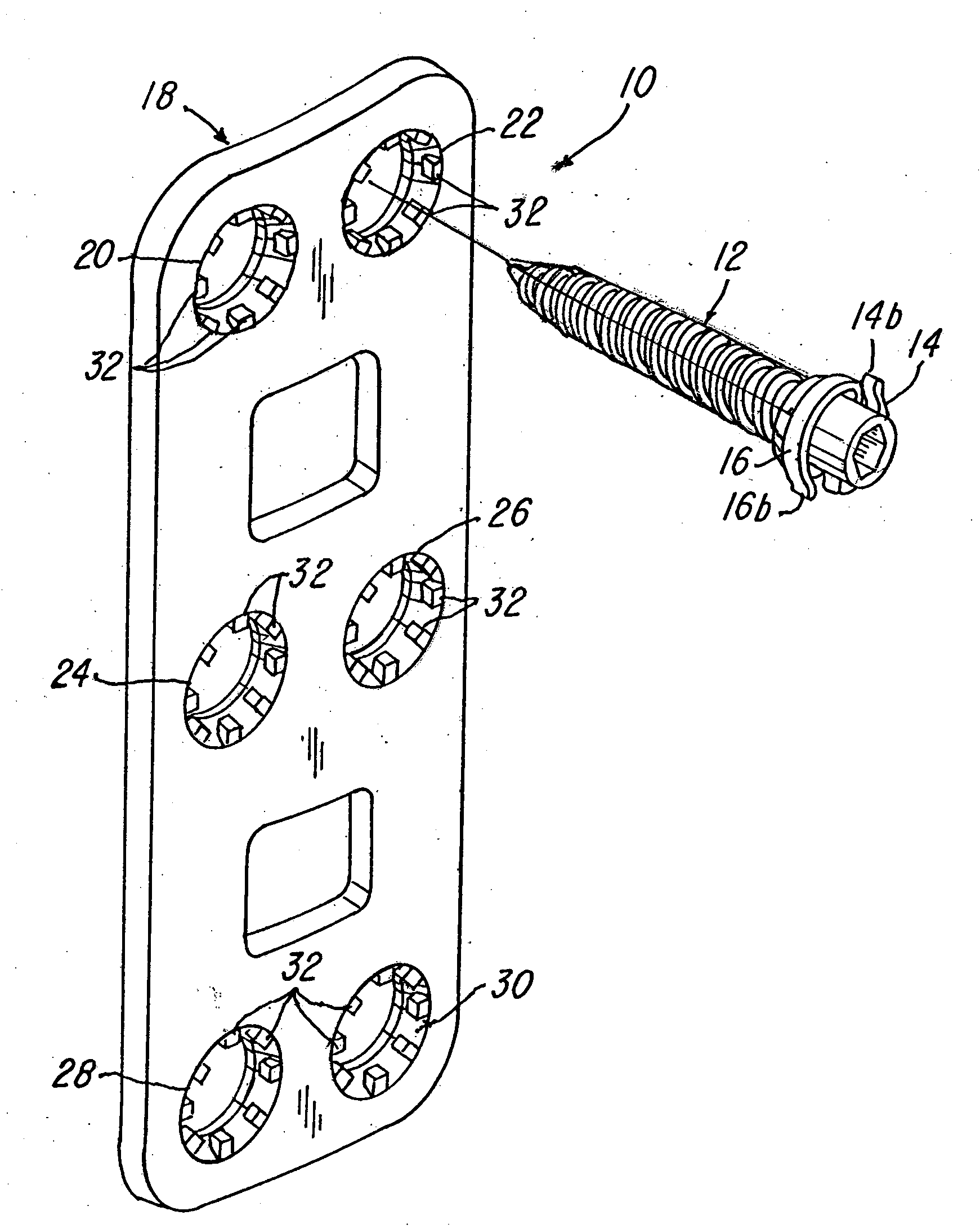
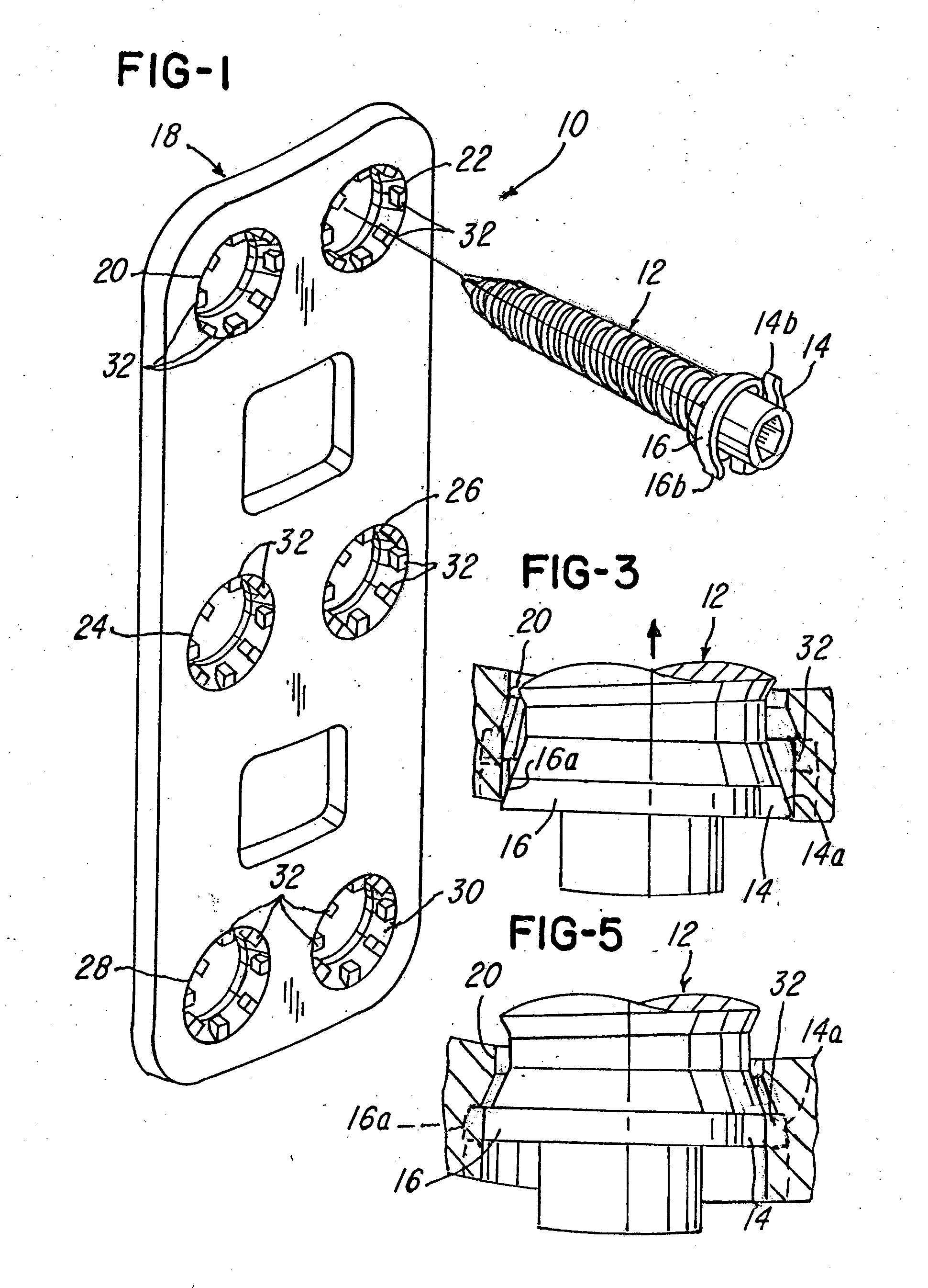
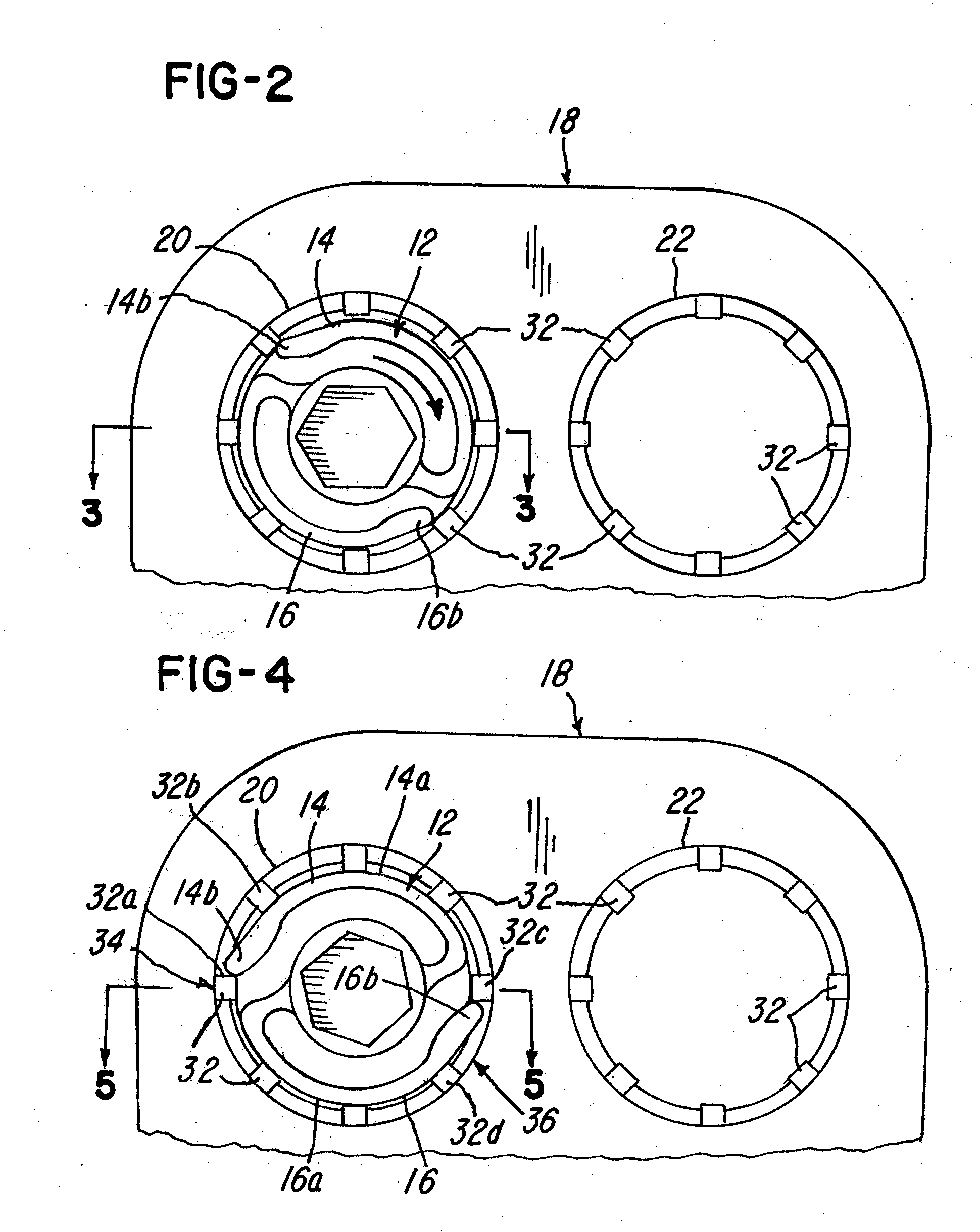
[0028]Referring now to FIGS. 1-17, means and apparatus for preventing axial and / or rotational movement in the form of a resilient lock may be provided. FIGS. 1-17 illustrate a system and method for providing an integral lock. In FIG. 1, a system 10 comprises a screw 12 comprises at least one or a plurality of resilient fingers, springs, pawls, elastic projections or members 14 and 16. The fingers or members are resilient, elastic and deflectable as with prior embodiments. In the illustration being described, the fingers or members 14 and 16 are integrally formed in the screw 12, but they could be non-integral or assembled from multiple parts.

[0029]Notice in the embodiment illustrated in FIGS. 1-5 that a plate 18 is provided having a plurality of apertures 20, 22, 24, 26, 28 and 30. In this embodiment, the plate 18 comprises a plurality of notches, projections or stops 32 associated with each aperture. The members 14 and 16 are normally biased a predetermined distance away from the a...


PUM


Abstract

Spinal fusion system and method utilizing an implant and screw, wherein at least one pawl is mounted on or integral with the screw to prevent said plate or screw from moving in at least one of an axial direction or a rotational direction.

Description

BACKGROUND OF THE INVENTION[0001]1. Field of the Invention[0002]This invention relates to a implant plate system, device and locking screw having at least one locking member. The preferred application for the device is in spinal surgery, however, applications in other areas of orthopedic surgery are appropriate.[0003]2. Description of the Related Art[0004]Many types of prosthetic devices have been proposed in the past. For example, U.S. Pat. No. 5,192,327 to Brantigan concerns a surgical prosthetic modular implant used singularly or stacked together to support and fuse together adjacent vertebrae or to totally or partially replace one or more vertebrae in a vertebral column. Other surgical implant devices and methods are shown in U.S. Pat. Nos. 4,488,543; 5,192,327; 5,261,911; 5,549,612; 5,713,899; 5,776,196; 6,136,002; 6,159,245; 6,224,602; 6,258,089; 6,261,586; 6,264,655; 6,306,136; 6,328,738; 6,361,537 and 6,592,586. Some or all of these devices have improved the success rate and...

Claims


Application Information

Patent Timeline
Patent Type & Authority Applications(United States)
IPC IPC(8): A61B17/70A61B17/56A61B17/04A61B17/58
CPCA61B17/8605A61B17/8052
Inventor KIRSCHMAN, DAVID LOUIS
Owner X SPINE SYST
Learn More