Method for weighing vehicles crossing a bridge

a technology for weighing vehicles and bridges, applied in liquid/fluent solid measurement, machines/engines, instruments, etc., can solve the problems of frequent maintenance, inconvenient detour routes, and high equipment and installation costs of systems

Inactive Publication Date: 2009-01-22
TATOM FR B +1
View PDF1 Cites 50 Cited by
  • Summary
  • Abstract
  • Description
  • Claims
  • Application Information

AI Technical Summary

Benefits of technology

[0012]The invention is a method for determining weight of a moving vehicle on a bridge. The method includes attaching sensors to the bridge, and includes mounting at least one discrete location vibration sensor to sense vibrations at a discrete location on the bridge, the sensor being responsive to low frequency vibrations. Such a sensor is mounted to a lower surface of the bridge pavement, the vibration sensor mounting being operative to mechanically couple wheel-generated low frequency pavement vibrations propagating through the pavement directly into the vibration sensor. The method further includes sensing low frequency pavement vibrations produced by a moving vehicle using at least one vibration sensor and providing sensor electrical output signals including those proportional to the low frequency pavement vibrations to a computing device. Using the computing device, the weight of the moving vehicle is determined using sensor output signals.

Problems solved by technology

Usually these bending members are installed in the pavement of a bridge approach, and less frequently are installed in pavement of a bridge deck because of significant difficulties encountered by such an installation on bridge spans.
These systems are also expensive in both equipment and installation costs.
Further, these systems experience frequent failures, especially on more heavily used bridges, because of high cycle deflection and fatigue of sensing members, thereby requiring frequent maintenance.
Because these sensors are installed in the bridge approach or bridge deck pavement, this maintenance requires disruption of traffic flow over what is typically a main traffic route, and these main routes usually have inconvenient detour routes available.
Furthermore, bridge approaches often have a concentration of nearby access ramps and service roads thereby making practical application of this system for bridge vehicular loading difficult or impossible to implement because of interfering seismic signals from vehicles traveling on nearby roadway approaches.
Significantly, Udd's system will be of little practical value for bridge applications because commonly there will be present more than one vehicle on a bridge; this is especially the case on bridges with longer spans and / or on moderately-to-heavily utilized bridges.
However, and as noted, this local strain information for a bridge cannot in general determine individual vehicle weight because local strain on a bridge is significantly influenced by weights and locations of all vehicles on the bridge span.
Consequently, this system cannot measure weights of individual vehicles because local strain in a bridge span is sensitive to weights of all vehicles in all lanes of the bridge span.
From the foregoing, the Udd system may provide useful information on the strains within bridge deck structure, but it is believed that this information, as disclosed, cannot be used for weigh-in-motion purposes to reliably measure weights of individual vehicles crossing a bridge.

Method used


Image

  • Method for weighing vehicles crossing a bridge
  • Method for weighing vehicles crossing a bridge
  • Method for weighing vehicles crossing a bridge

Examples


Embodiment Construction

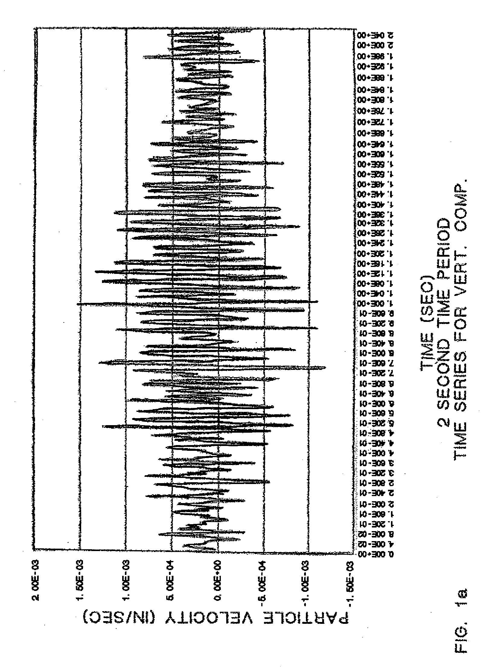
Vehicle Generated Vibration in Bridge Pavement

[0024]Whenever in motion, a vehicle encounters rolling resistance on a roadway or on a bridge. The rolling resistance includes the vehicle interaction with the bridge deck pavements. In order to continue its motion, the vehicle must supply energy at a rate sufficient to overcome this rolling resistance. Based on automotive engineering studies, the rolling resistance, Rr, of a vehicle wheel is related to the vehicle weight, W, and the rolling resistance coefficient, K, according to the relation,

Rr=KW

The rolling resistance coefficient, K, is weakly dependent on pavement temperature and moisture content, but is approximately equal to 0.012 under normal driving conditions. If the vehicle moves with speed, V, the energy rate to overcome the resistance is

ER=RrV

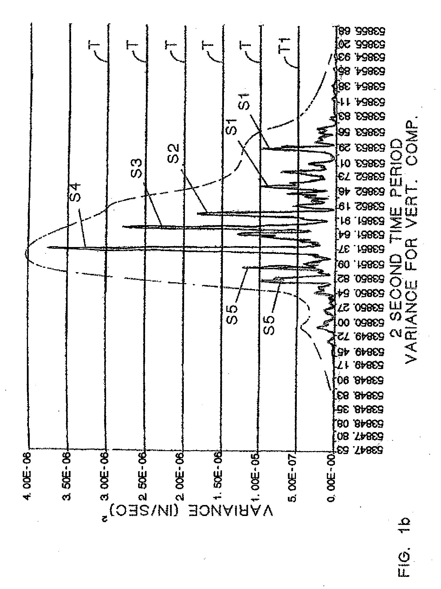
The energy rate, ER, is defined as

ER=Ci∑n=1Nσi2,n

where[0025]Ci=correlation coefficient for ith component of particle velocity[0026]N=total number of samples in sample interval[0027]n=sam...


PUM


Abstract

A method for weighing vehicles moving on a bridge deck pavement is provided. At least one vibration sensor is mounted on a lower side of the pavement to sense low frequency pavement vibrations generated by moving vehicle wheels and propagated in waves in the pavement. Vibration sensor output signals are provided to a computing device. Sensed vibration energy rate is computed and, with signals from vibration sensors mounted at two locations separated by a known longitudinal distance, vehicle speed is also computed. The weight of the vehicle is determined as the product of a calibration coefficient and the ratio of sensed vibration energy rate to velocity. Using vibration sensor signals indicative of wheel generated vibrations in the very near field and summing vibration energy rates computed from these signals during vehicle passage over the vibration sensors the weight of individual vehicles is computed when other moving vehicles are present.

Description

CROSS REFERENCE TO RELATED APPLICATIONS[0001]This application is a continuation-in-part of U.S. utility application Ser. No. 11 / 545,905, filed Oct. 11, 2006, which claims the benefit of provisional application No. 60 / 725,592, filed Oct. 11, 2006.FIELD OF THE INVENTION[0002]This invention relates generally to weigh-in-motion systems for measuring weight of moving vehicles, and particularly for measuring weight of vehicles as they cross bridges, overpasses or similar structures in order to monitor the vehicular loading of structures.BACKGROUND AND RELATED ART[0003]For purposes of this application, the term “bridge” as used herein refers to bridges that cross natural or manmade boundaries or obstacles, such as rivers and streams, ravines, canyons or the like, structures that cross underlying roads, railroads or any other structural contrivance having a free space thereunder and which conveniently connects two points for the purpose of facilitating movement of vehicular traffic. Further...

Claims


Application Information

Patent Timeline
Patent Type & Authority Applications(United States)
IPC IPC(8): G06F19/00
CPCG01G23/3728G01G19/022
Inventor TATOM, FRANK B.HARNDON, GEORGE W.
Owner TATOM FR B
Why Eureka
Try Eureka