Mechanical plug and method for using the same

a technology of mechanical plugs and plugs, which is applied in the direction of mechanical equipment, auxiliaries of forms/shuttering/falseworks, building repairs, etc., can solve the problems of increased construction costs, loose plug types, and inability to meet the needs of use, and achieves convenient installation and replacement, superior results, and low construction costs.

Inactive Publication Date: 2009-01-29
GREENSTREAK GROUP
View PDF25 Cites 17 Cited by
  • Summary
  • Abstract
  • Description
  • Claims
  • Application Information

AI Technical Summary

Benefits of technology

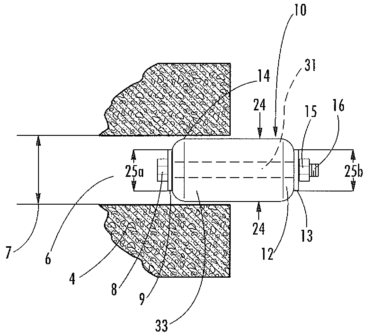
[0006]In accordance with the present invention, a mechanical plug is provided to seal an opening in a structure. Although the plug may be used to seal any suitable opening, this specification discusses the use of the plug in relation to sealing an opening created by the removal of a reusable tie rod in a concrete wall. The plug of the present invention is inexpensive in construction, easy to install and replace, and provides a superior result when compared with other devices and methods that are currently available.

Problems solved by technology

These openings result in an unacceptable construction if the function of the concrete structure requires the creation of a barrier against water and pests.
However, these types of plugs can become loose or even ejected from the openings if a large amount of water pressure acts on the opening.
One problem is that the tapered tie rods are required to be aligned so that their larger diameter side is facing the direction that is more likely to receive higher pressure.
This results in increased construction costs since each tie rod must be analyzed to determine the direction of its taper.
A leak could result if one tie rod was backwards or if pressure was applied to the small diameter side of the opening.
Another problem is that the system requires that the resilient plugs are inserted into the larger diameter opening (i.e. the resilient plugs cannot be inserted into the end of the opening having the smaller diameter because the plugs are too big).
Yet another problem with the use of the resilient plugs with tapered openings system relates to fixing leaks that occur after the concrete structure is created.

Method used


Image

  • Mechanical plug and method for using the same
  • Mechanical plug and method for using the same
  • Mechanical plug and method for using the same

Examples


Embodiment Construction

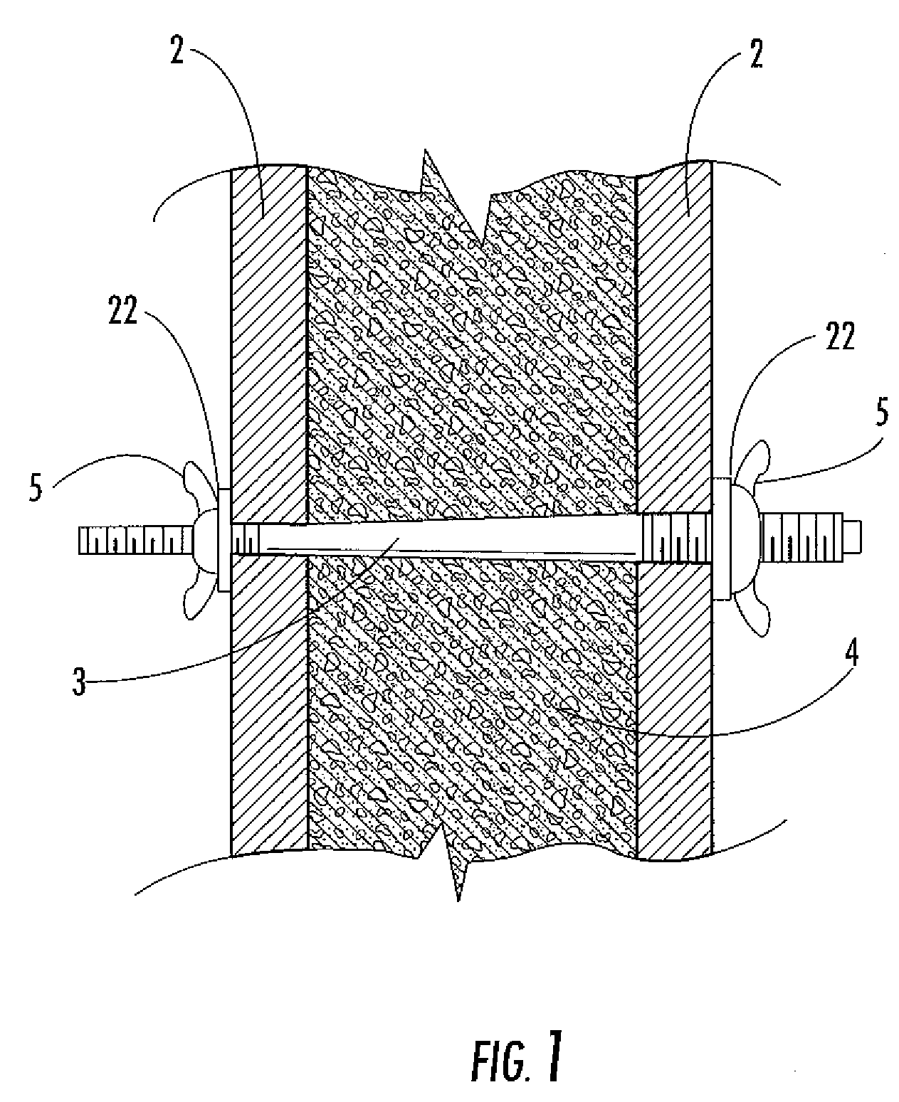
[0014]FIG. 1 of the drawings shows a typical wall construction utilizing a reusable tapered tie rod 3. A pair of wall forms 2 are held in place by the tie rod 3 preventing the wall forms 2 from spreading apart when concrete 4 is poured between them. Threaded on opposite ends of the tie rod 3 are washers 22 or the like, with threaded wing nuts 5 or the like used to fasten and secure the tie rod 3 and the formwork 2. The tie rod 3 preferably comprises a smooth tapered main body section 3 which permits withdrawal of the tie rod 3 during removal of the formwork after the concrete wall 4 is poured, thereby creating a smooth surfaced opening 6 in the concrete wall 4, as shown in FIG. 2.

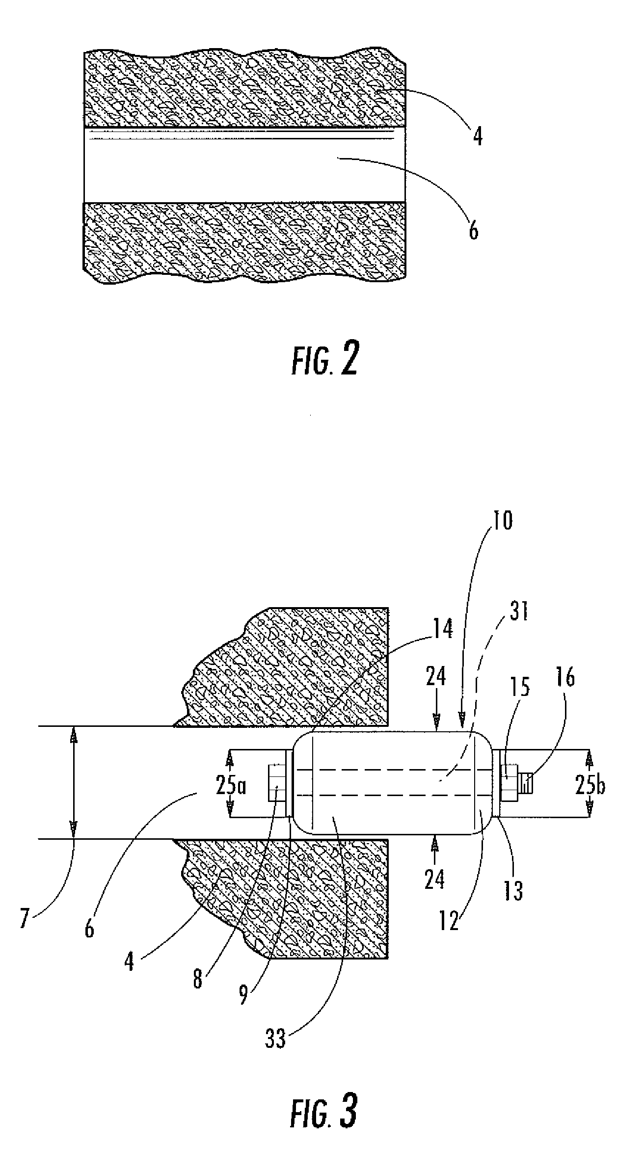
[0015]After removal of the tie rod 3, the resulting opening 6 in the concrete wall 4 must be sealed to prevent water, moisture, dirt, or pests from being able to penetrate through the wall 4. To seal this opening 6, in accordance with the present invention, a plug 10 is provided. Different embodiments of th...


PUM


Abstract

A plug designed to seal an opening formed in a concrete wall. The plug comprises a main body portion, a first end, and a second end wherein the first end and second end are combined by a bolt having a fastener on one end. Washers are combined with the bolt on each end of the plug. The plug has a first diameter wherein it can be inserted into the opening and a second diameter wherein it plugs the opening in the wall. The plug is moved from its first position to its second position by tightening the fastener thereby squeezing the plug between the two washers. This tightening causes an expansion of the plug to its second position, increasing its diameter inside the opening and forming a seal between the plug and the wall of the opening.

Description

[0001]This application claims priority under 35 USC 119 to Provisional Patent Application Ser. No. 60 / 898,687 filed on Feb. 1, 2007, the contents of which are hereby incorporated by reference.BACKGROUND OF THE INVENTION[0002]In the construction of houses, water / wastewater treatment tanks, and other structures, widespread use is made of poured concrete for foundations. Typically, concrete foundations and tank walls are formed in wooden or steel forms into which the concrete is poured. The forms are secured in spaced relation by steel tension rods (tie rods). After the concrete hardens (sets), the tie rods and forms are removed leaving the concrete structure with a number of openings extending therethrough. These openings result in an unacceptable construction if the function of the concrete structure requires the creation of a barrier against water and pests.[0003]Many different types of plugs have been developed to plug the types of openings that are left in concrete structures afte...

Claims


Application Information

Patent Timeline
Patent Type & Authority Applications(United States)
IPC IPC(8): E04G17/06E04F19/00F16B13/04F16B13/14E04G23/02
CPCE04G17/0644F16B13/0841E04G17/0652
Inventor HEMMINGER, MATTHEWWIEBKE, AARON
Owner GREENSTREAK GROUP
Why Eureka
Try Eureka