Method and Apparatus for Collecting and/or Removing Sludge

a technology for removing sludge and collecting methods, applied in water cleaning, liquid displacement, separation processes, etc., can solve the problems of heavy machinery and environmental pollution, and achieve the effect of small footprin

Active Publication Date: 2009-01-29
ULTRA AQUATIC TECH
View PDF16 Cites 16 Cited by
  • Summary
  • Abstract
  • Description
  • Claims
  • Application Information

AI Technical Summary

Benefits of technology

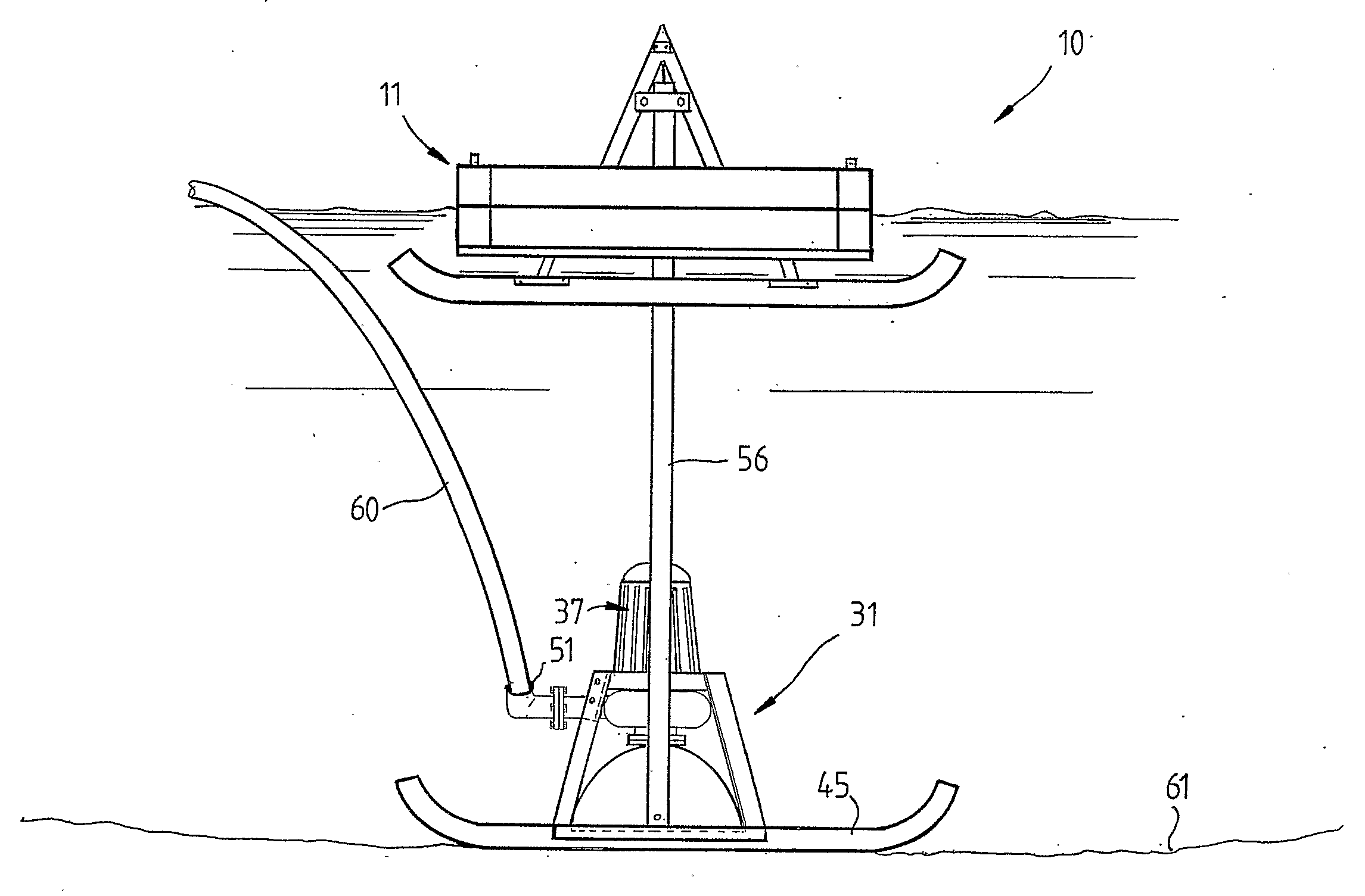
The patent describes a device that helps to control the depth of a suction head assembly used in construction. The device includes guide means, which are elongated members that are placed upright to show the depth of the assembly. These guide means are connected to the suction head assembly and are guided by the float members, which are slide members. The guide means prevent the suction head assembly from twisting and allow it to move vertically beneath the float assembly, keeping the device's footprint small. Overall, the device helps to ensure accurate and safe control of the suction head assembly during construction.

Problems solved by technology

The technical problem addressed by this patent is how to effectively remove sludge and other solid materials from liquids like ponds without having to drain them first, reducing costs associated with waste removal and minimizing negative impacts on the environment.

Method used


Image

  • Method and Apparatus for Collecting and/or Removing Sludge
  • Method and Apparatus for Collecting and/or Removing Sludge
  • Method and Apparatus for Collecting and/or Removing Sludge

Examples


Embodiment Construction

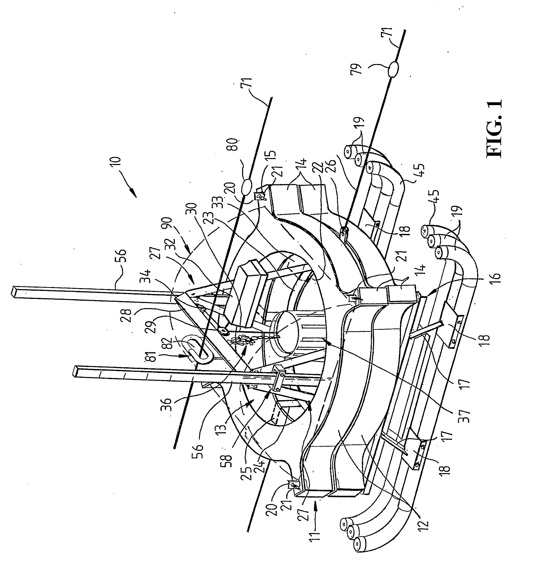
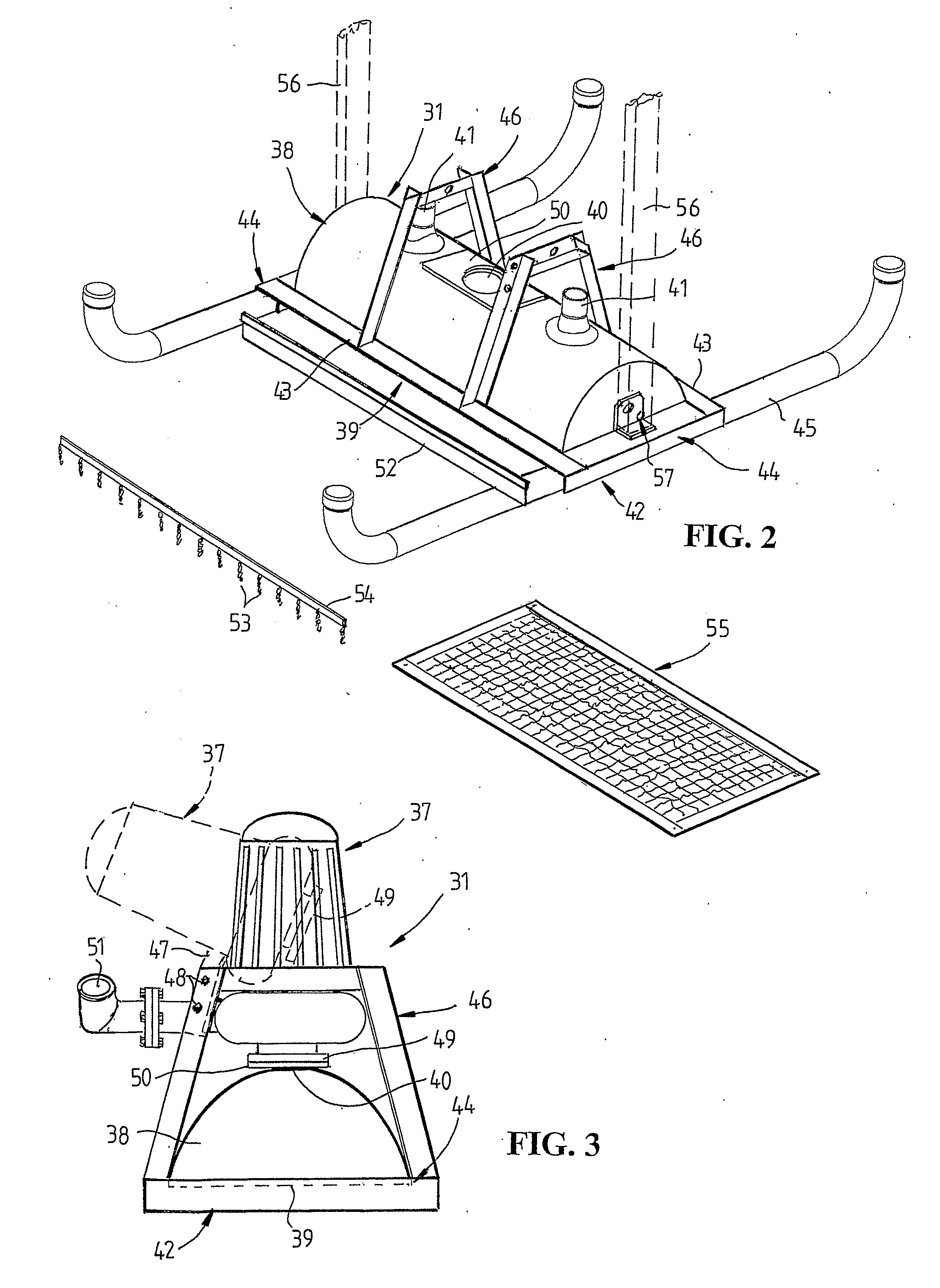
[0032]Referring firstly to FIG. 1, there is illustrated a sludge harvester 10 according to an embodiment of the invention for removing sludge or other material settling on or adjacent the floor of a liquid reservoir such as an effluent pond or other settling pond or for removing materials suspended in liquid in a pond. The sludge harvester 10 includes a float assembly 11 which includes in this embodiment a pair of annular hollow float members 12 having a hollow interior, each float member 12 serving as an air reservoir and for this purpose being sealed to contain air and act as a float. Alternatively, one or more buoyant bodies such as foam plastics members or inserts such as members or inserts of tubular configuration may be located in the hollow float member 12. In an alternative arrangement, a buoyant foam plastics material may be injected into a hollow float member 12. Each hollow float member 12 is provided with circumferentially spaced radially extending lugs 14 having apertur...


PUM

PropertyMeasurementUnit
Pressureaaaaaaaaaa
Depthaaaaaaaaaa
Sliding frictionaaaaaaaaaa

Abstract

Apparatus for removing solids such as sludge from a liquid reservoir comprising a float, a suction head assembly carrying a pump, and elongated guides interconnecting the suction head assembly and float. The float also carries a winch for raising and lowering the suction head assembly. The guides are slidably engaged with the float and serve to indicate the depth of operation of the suction head assembly.

Description


Claims


Application Information

Patent Timeline
Owner ULTRA AQUATIC TECH
Why Eureka
Try Eureka