Supercharge Your Innovation With Domain-Expert AI Agents!

Forming method for fiber reinforced resin

a fiber reinforced resin and forming method technology, applied in the direction of lamination, lamination apparatus, chemical equipment and processes, etc., can solve the problems of poor mechanical strength and inability to avoid the generation of air bubbles, and achieve the effects of improving mechanical strength, reducing air bubbles, and improving mechanical strength

Inactive Publication Date: 2009-01-29
YUAN MIN AN ENTERPRISE
View PDF4 Cites 0 Cited by
  • Summary
  • Abstract
  • Description
  • Claims
  • Application Information

AI Technical Summary

Benefits of technology

[0006]The present invention has been accomplished under the circumstances in view. It is one object of the present invention to provide a forming method for fiber reinforced resin, which can remove air bubbles inside the fiber reinforced resin effectively.
[0007]It is another object of the present invention to provide a forming method for fiber reinforced resin, the product of which has improved mechanical strength.
[0008]To achieve these and other objects of the present invention, the forming method for fiber reinforced resin includes the following steps. First, put a stack of pre-pregs into a cavity of a die having a plurality of openings in communication with the cavity and the space outside the die. Then heat the die and exhaust air through the openings from the cavity of the die. Thus, the air bubbles between the pre-pregs as well as surplus resin can be drawn out such that the product has improved mechanical strength.

Problems solved by technology

In accordance with technology level nowadays, it is not possible to avoid the generation of the air bubbles 8 between pre-pregs while stacking the pre-pregs.
The number of the air bubbles 8, i.e. structural defects, in the product formed by this way is still large such that the mechanical strength is poor.

Method used


Image

  • Forming method for fiber reinforced resin
  • Forming method for fiber reinforced resin
  • Forming method for fiber reinforced resin

Examples


first embodiment

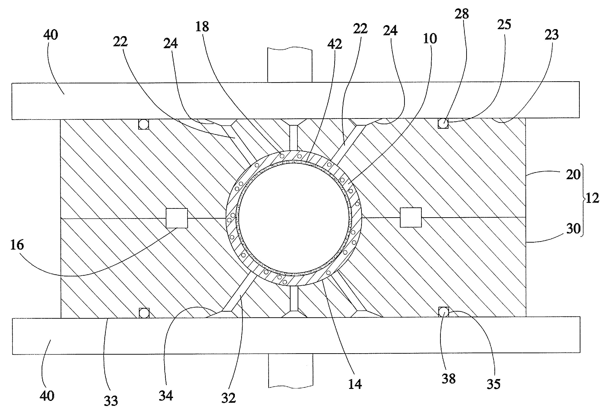
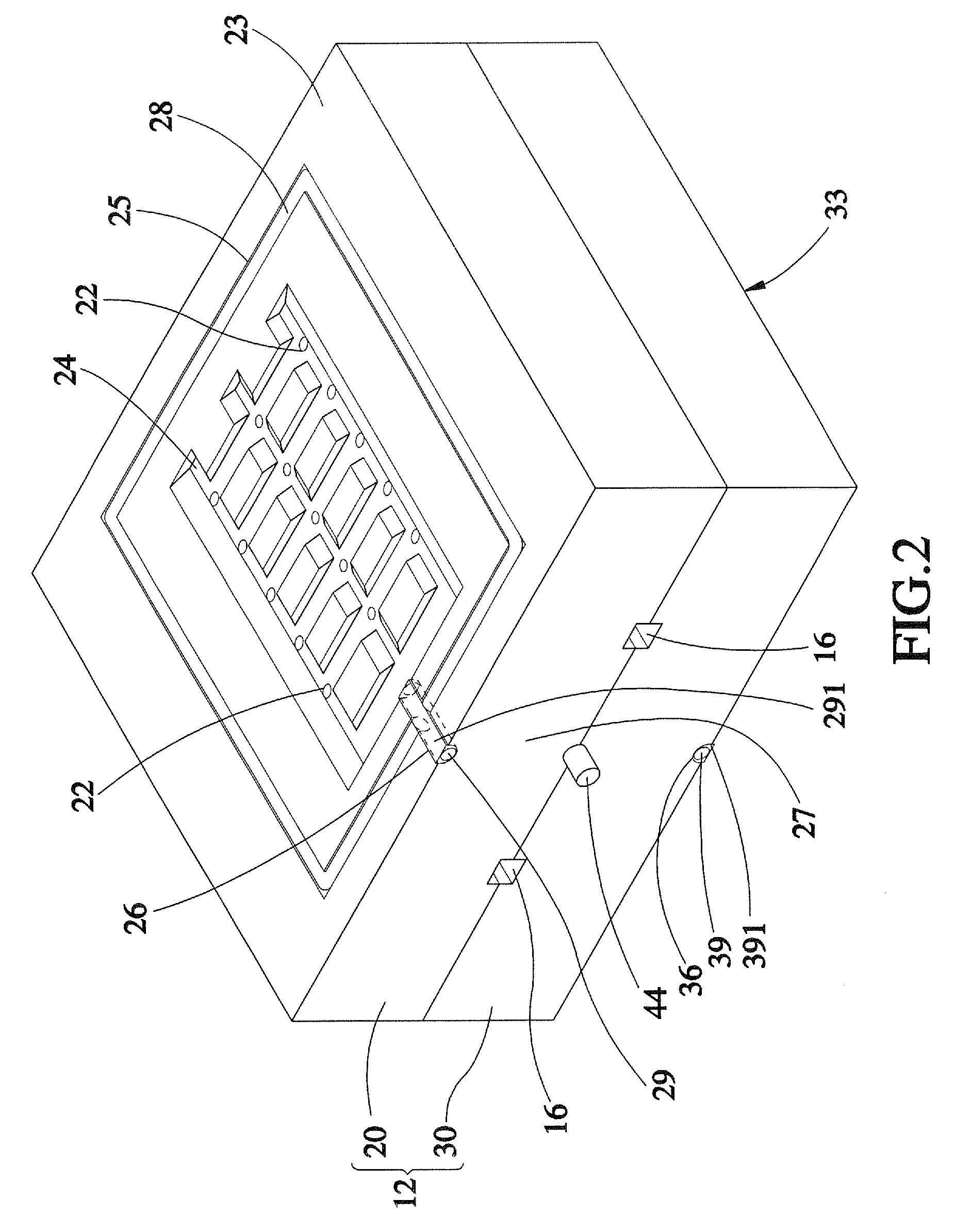
[0014]Referring to FIGS. 2-3, a forming method for fiber reinforced resin in accordance with the present invention comprises the following steps. First, roll a stack of pre-pregs into a tube 10 and then put the tube 10 into a cavity 14 of a die 12. The fiber of the pre-pregs can adopt but not limit to carbon fiber, glass fiber, boron fiber or Kevlar fiber. The resin of the pre-pregs can adopt thermosetting resin or thermoplastic resin. The die 12 consists of an upper die 20 and a lower die 30. An annular groove 16 surrounding said cavity 14 is defined between the upper die 20 and the lower die 30.

[0015]The upper die 20 is provided with a plurality of opening 22 in communication with the cavity 14 and the space outside the die 12. A top surface 23 of the upper die 20 is provided with a trough 24, an annular channel 25 surrounding said trough 24, and a receiving trench 26 extending from said trough 24 to a side surface 27 of the upper die 20. The openings 22 are located within the tro...

third embodiment

[0020]The method adopted by aforesaid two embodiments is so-called inner pressure method. The spirit of the present invention can be applied to outer pressure method. As shown in FIG. 5, the die 80 adopted by the forming method in accordance with the present invention comprises an upper die 81, a lower die 82 and a cavity 83 defined between the upper die 81 and the lower die 82. The upper die 81 is provided with two openings 86. The method comprises the steps of putting several pre-pregs layer by layer into a sheet 84, and then putting the sheet 84 into the cavity 83, and then heating the die 80 with the two heating boards 85 and exhausting air through the openings 86. There is no need to pump high pressure air into the envelope inside the tube as the inner pressure method. In this embodiment, exhausting air through the openings 86 of the upper die 81 is efficient enough to draw out the air bubbles in the sheet 84 since the sheet 84 is relatively thin. The lower die 82 may be provid...


PUM

PropertyMeasurementUnit
pressureaaaaaaaaaa
mechanical strengthaaaaaaaaaa
period of timeaaaaaaaaaa

Abstract

A forming method for fiber reinforced resin includes the following steps. First, put a stack of pre-pregs into a cavity of a die having a plurality of openings in communication with the cavity and the space outside the die. Then heat the die and exhaust air through the openings from the cavity of the die. Thus, the air bubbles between the pre-pregs as well as surplus resin can be drawn out such that the product has improved mechanical strength.

Description

BACKGROUND OF THE INVENTION[0001]1. Field of the Invention[0002]The present invention relates to fiber reinforced resin and more particularly, to a forming method for fiber reinforced resin, which can remove air bubbles inside the fiber reinforced resin effectively such that the product has improved mechanical strength.[0003]2. Description of the Related Art[0004]As shown in FIG. 1, a conventional forming method for fiber reinforced resin is to roll a stack of pre-pregs into a tube 1, then put the tube 1 into a cavity 3 of a die 2. The die 2 consists of an upper die 4 and a lower die 5 between which an annular resin groove 6 surrounding the cavity 3 is defined. Heat the die 2 with two heating board 7 and pump high pressure air into an envelope 91 inside the tube 1 such that the tube 1 is inflated to stop against the periphery of the cavity 3. The tube 1 is then cured after a period of time.[0005]In accordance with technology level nowadays, it is not possible to avoid the generation...

Claims


Application Information

Patent Timeline
Patent Type & Authority Applications(United States)
IPC IPC(8): B29C70/46
CPCB29C70/46B29C70/44
Inventor YU, KUO-PIN
Owner YUAN MIN AN ENTERPRISE
Features
  • R&D
  • Intellectual Property
  • Life Sciences
  • Materials
  • Tech Scout
  • Unparalleled Data Quality
  • Higher Quality Content
  • 60% Fewer Hallucinations
Learn More