Air bubble removing device for infusion tube and an infusion device
A technology for infusion tubes and air bubbles, which is applied in the field of sterile medical devices to achieve the effect of eliminating air bubbles
- Summary
- Abstract
- Description
- Claims
- Application Information
AI Technical Summary
Problems solved by technology
Method used
Image

Examples
Embodiment 1
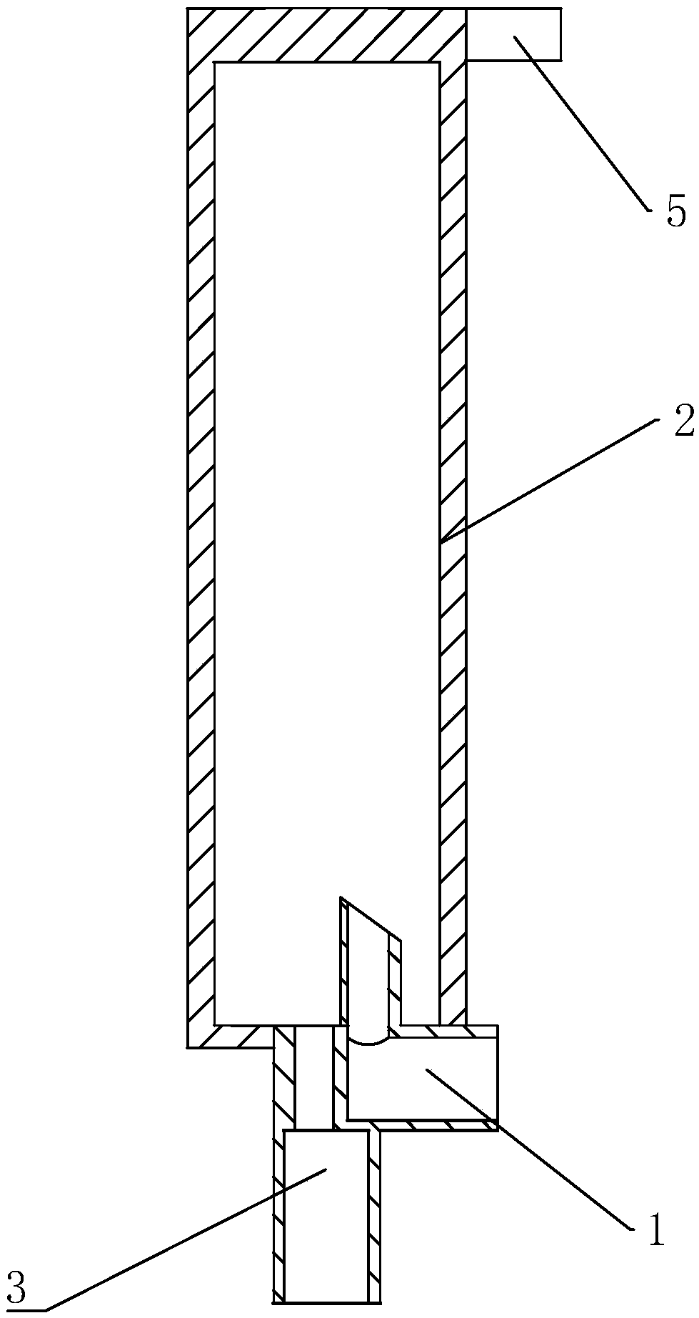
[0039] Embodiment one: infusion tube air bubble removal device, such as Figure 1-2 As shown, the bubble removal chamber 2 is included, and the lower end of the bubble removal chamber 2 is connected with a liquid inlet channel 1 and a liquid outlet channel 3. The liquid inlet channel 1 is arranged at a corner. Preferably, the liquid inlet channel 1 is arranged at a right angle, and the liquid inlet channel 1 is arranged at a right angle. The beginning of the channel 1 is connected to the upper infusion tube 7, the beginning of the liquid inlet channel 1 is arranged perpendicular to the installation direction of the air removal chamber 2, and the terminal of the liquid inlet passage 1 is arranged upward along the installation direction of the air removal chamber 2; 3 can be arranged in a corner or in a straight line, regardless of whether the liquid outlet channel 3 is arranged in a corner or in a straight line, but the terminal of the liquid outlet channel 3 is arranged downwar...
Embodiment 2
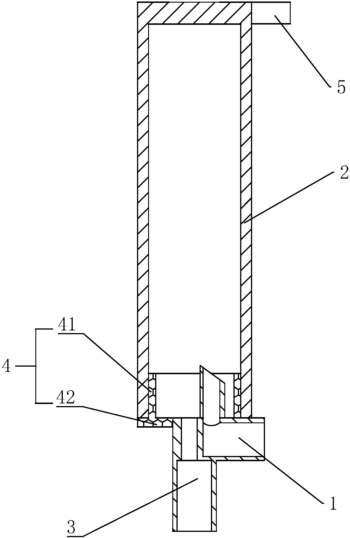
[0042] Embodiment two: infusion tube air bubble removal device, such as image 3 As shown, the difference between Embodiment 2 and Embodiment 1 is that the lower end of the debubble chamber 2 is detachably connected with a connecting seat 4 for connecting the liquid inlet channel 1 and the liquid outlet channel 3, and the debubble chamber 2 and the fixing part are integrated Molded setting, the connecting seat 4 and the liquid inlet channel 1 and the liquid outlet channel 3 are integrally formed and set.
[0043] The connecting seat 4 includes a connecting ring 41 and a connecting bottom wall 42. The connecting ring 41 is socketed with the air-removing chamber 2, wherein the connecting ring 41 is socketed at the lower end of the air-removing chamber 2, or the lower end of the air-removing chamber 2 is sleeved. Connected to the connecting ring 41, the selection of any of the above-mentioned technical solutions in the present invention has no effect on the realization of the pur...
Embodiment 3
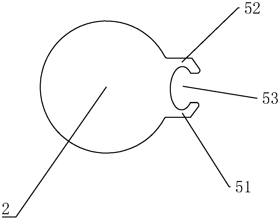
[0046] Embodiment three: infusion tube debubble device, such as Figure 4-5 As shown, the difference between the third embodiment and the second embodiment is that the upper end of the debubbling chamber 2 is provided with an injection hole 21 communicating with the outside world, and the inner wall of the injection hole 21 is provided with a card slot 211, and a card slot 211 is installed in the card slot 211. The adapted flexible injection part 6 is engaged with the slot 211, wherein the flexible injection part 6 can be made of soft elastic materials such as rubber.
[0047] In the specific implementation process of the third embodiment, the infusion tube de-bubble device needs to be turned upside down to fill the de-bubble chamber 2 with liquid medicine, and the bubbles flow through the upper infusion tube 7 and the liquid inlet channel 1 and then float up to the de-bubble chamber 2 However, the medicinal liquid continues to flow through the liquid outlet channel 3 and ente...
PUM
 Abstract
Description
Claims
Application Information