Split cores for motor stator, motor stator, permanent magnet type synchronous motor and punching method by split core punching die

a technology of split cores and stators, which is applied in the direction of stator/rotor bodies, synchronous machines with stationary armatures, rotating magnets, etc., can solve the problems of limited production costs, large die size, and complicated work, so as to reduce the cogging torque attributed to accuracy, improve the rigidity of the cores when connected together, and improve the effect of assembling accuracy

Active Publication Date: 2009-01-29
YASKAWA DENKI KK
View PDF7 Cites 51 Cited by
  • Summary
  • Abstract
  • Description
  • Claims
  • Application Information

AI Technical Summary

Benefits of technology

[0048]By the configurations described above, since the ends of the yokes and the pole pieces at both ends of the teeth are displaced in the one circumferential direction by laminated iron core, the cogging torque is made equal and the rigidity of the cores when they are connected together is increased, and because of this, the assembling accuracy is improved and hence, cogging torque attributed to accuracy can be reduced, whereby smooth rotation can be obtained.
[0049]In addition, since the circumferential displacement of the iron cores is increased by displacing the iron cores of the split cores in the one direction towards the center laminated layer thereof and then displacing the iron cores of the split cores in the opposite direction from the center laminated layer thereof, the rigidity is increased further so as to reduce the cogging torque. In particular, a large advantage is provided for a long motor in which a large number of cores are laminated.
[0050]Since the cogging torque is reduced in the way described above while the teeth are not displaced, the winding operation of windings can be simplified.
[0051]Furthermore, since the productivity in punching out cores can be increased and the cores are grouped into the plurality of blocks, the productivity can be increased further.
[0052]In addition, by the punching method by the die of the invention, since the length of the tooth portions can be changed minutely by a rotary cutting blade built in a progressive die, a smooth skew can simply be obtained.

Problems solved by technology

(1) In the event that a skew cannot be given to the stator, the magnets need to be shifted in a radial direction on the rotor side so that a skew is given to the rotor, and this work has been complicated.
(2) In addition, in the event that a smooth skew is given to the stator core, a cutting blade has to be prepared for each type of skew given, which has been difficult from the viewpoint of die size and limited production costs.

Method used


Image

  • Split cores for motor stator, motor stator, permanent magnet type synchronous motor and punching method by split core punching die
  • Split cores for motor stator, motor stator, permanent magnet type synchronous motor and punching method by split core punching die
  • Split cores for motor stator, motor stator, permanent magnet type synchronous motor and punching method by split core punching die

Examples


embodiment 1

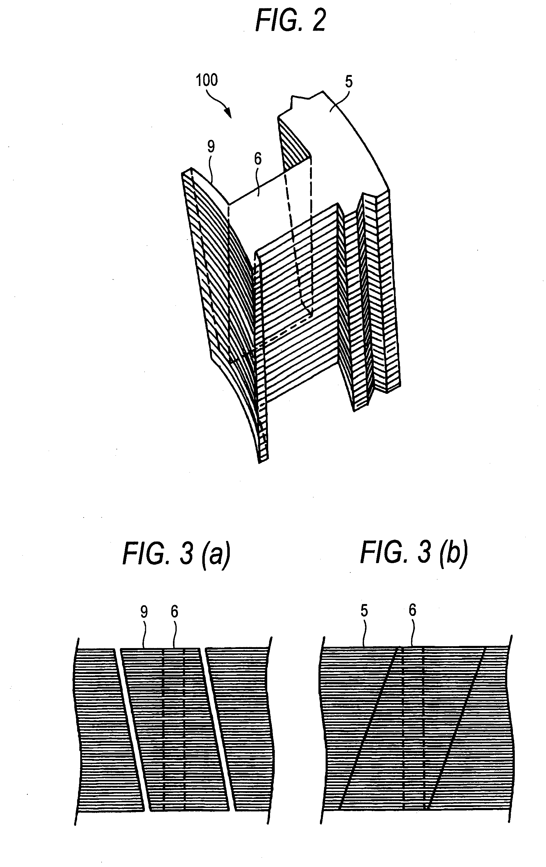
[0080]FIGS. 2 and 3 are diagrams which describe split cores according to Embodiment 1 of the invention, of which FIG. 2 is a perspective view and FIG. 3 shows sectioned side views of split cores of Embodiment 1 when they are connected together as viewed from the side of pole pieces (a) and the side of yokes (b), respectively. When a sheet of electromagnetic steel is punched out by the press, only both ends of a yoke and a pole piece at a distal end of a tooth are rotated in a circumferential direction by laminated iron core every time the sheet is punched out.

[0081]When a large number of split cores shown in FIG. 2 are laminated to form a stator laminated iron core 100, as is shown in FIGS. 3(a) and 3(b), since pole pieces 9 and yokes 5 are displaced in one circumferential direction, cogging torque is made equal, and since the rigidity of the split cores when they are connected together is increased, the assembling accuracy is improved, whereby cogging torque attributed to accuracy ...

embodiment 2

[0083]FIGS. 4 and 5 are diagrams which describe split cores according to Embodiment 2 of the invention, of which FIG. 4 is a perspective view and FIG. 5 shows sectioned side views of split cores of Embodiment 2 when they are connected together as viewed from the side of pole pieces (a) and the side of yokes (b), respectively. When a sheet of electromagnetic steel is punched out by the press, both ends of a yoke and a pole piece at a distal end of a tooth are rotated, by laminated iron core, in such a manner that the direction of displacement is changed at a central portion in a longitudinal direction when split cores so punched out are laminated.

[0084]When a large number of split cores shown in FIG. 4 are laminated to form a stator laminated iron core 200, as is shown in FIGS. 5(a) and 5(b), since pole pieces 9 and yokes 5 are displaced in one circumferential direction to a center laminated layer and are then displaced in an opposite direction downwards from the center laminated lay...

embodiment 3

[0087]FIGS. 6 and 7 are diagrams which describe split cores according to Embodiment 3 of the invention, of which FIG. 6 is a perspective view and FIG. 7 shows sectioned side views of split cores of Embodiment 3 when they are connected together as viewed from the side of pole pieces (a) and the side of yokes (b), respectively. When a sheet of electromagnetic steel is punched out by the press, only a pole piece at both ends of the teeth is rotated in a circumferential direction by laminated iron core.

[0088]When a large number of split cores shown in FIG. 5 are laminated to form a stator laminated iron core 300, as is shown in FIGS. 7(a) and 7(b), since pole pieces are displaced in one circumferential direction, cogging torque is made equal, and teeth are not twisted but are in a straight line, thereby making it possible to make the winding work of windings simple and easy.


PUM

PropertyMeasurementUnit
thicknessaaaaaaaaaa
diameteraaaaaaaaaa
widthaaaaaaaaaa

Abstract

Although in a conventional permanent magnet type synchronous motor, cogging torque is reduced by displacing permanent magnets of a rotor in a circumferential direction or displacing a stator core in a circumferential direction, since the skew so produced reduces the output of the motor and moreover the winding work of windings cannot be automated to make the resulting motor highly expensive, split cores are provided which solves those problems and enables the winding work of windings to be automated so as to obtain an inexpensive and high-output motor.There are provided a plurality of split cores (100) made up of laminated iron cores each having formed thereon a tooth (6), and a yoke (5) and a pole piece (9) which are made to connect to the tooth (6) at both ends thereof, and arranged and connected together into an annular shape to make up a stator, characterized in that both ends of the yokes (5) and both ends of the pole pieces (9) are displaced in one circumferential direction by laminated iron core from a top laminated layer to a bottom laminated layer of the iron cores of the split cores.

Description

TECHNICAL FIELD[0001]The present invention relates to a permanent magnet type synchronous motor which is required to operate smoothly in the field of FA such as machining tools and more particularly to split cores for a motor stator, the motor stator, and a punching method by a split core punching die.BACKGROUND ART[0002]In a conventional motor, a permanent magnet of a rotor is divided in an axial direction to constitute blocks, and the blocks are arranged while being displaced in a circumferential direction so that a skew effect is imparted to the motor. Since the blocks are arranged so as to have axial spaces therebetween, no leakage of magnetic flux is generated in an axial component, and hence, a magnetic flux distribution in a circumferential direction becomes a sine wave, whereby a cogging torque in each block is reduced (for example, Patent Document No. 1).[0003]In addition, skew slots for displacing a stator continuously in a circumferential direction are widely known, and s...

Claims


Application Information

Patent Timeline
Patent Type & Authority Applications(United States)
IPC IPC(8): H02K1/12H02K15/02
CPCH02K1/148Y10T29/49009H02K2201/06H02K15/022H02K21/16
Inventor TOMOHARA, KENJIMIYAZAKI, SEIJIKOGA, MITSUHIROMATSUMOTO, MAKOTOKOGA, HIROSHISAKAMOTO, SHINICHI
Owner YASKAWA DENKI KK
Why Eureka
Try Eureka