Supercharge Your Innovation With Domain-Expert AI Agents!

RFID Tag Containing Two Tuned Circuits

Inactive Publication Date: 2009-01-29
HID TEXTILE SERVICES SARL
View PDF9 Cites 32 Cited by
  • Summary
  • Abstract
  • Description
  • Claims
  • Application Information

AI Technical Summary

Benefits of technology

[0023]The first tuned circuit may be inductive and the second tuned circuit may be capacitive. The relative phases of currents in the circuits preferably range between 90 and 180 degrees. When several tags are stacked in close proximity, many inductors (first and second) may be well coupled with a range of currents up to + / −90 degrees from the carrier field. The extra second inductor may allow more inductors to be in close coupling relationship with each other (eg. a stack of 30 tags has 60 inductors). This may give rise to a mix of amplitudes and phases of magnetic field causing ripples in the resonance curve as each inductor is coupled to many inductors. If a peak of one of the ripples is arranged so that it occurs at the frequency of the carrier then extra tag performance may be obtained.
[0024]The inductor or coil associated with the first tuned circuit may be smaller in size and / or length than the inductor or coil associated with the second tuned circuit such that when the inductors are aligned on either side of an insulating substrate with one edge directly above the other, a region may exist in which the smaller first inductor causes flux to pass through an axial region of the second inductor in an opposite direction to flux flowing in the axial region of the rest of the second inductor. The region of opposite flux direction may lower the coupling factor from a value close to unity, for equal size loops, to around 0.7 wherein a coupling factor of 1 denotes that all of the flux of the first inductor passes through the second inductor.
[0027]For a single tag, the second tuned circuit may couple to the first tuned circuit with a coupling factor of around 0.7. However, because the second tuned circuit is further removed from the carrier frequency, the current flowing in the second tuned circuit may be relatively small due to the energising field and may have a relatively small effect on the first tuned circuit, the effect being a lowering of the resonant frequency of the first tuned circuit.

Problems solved by technology

A problem arises when tags to be read or written are in close proximity.
Tags in close proximity are subject to detuning effects particularly when the tags are stacked on a common axis.
However, this type of compensation is not very successful when spacings between the tags are less than about 10 mm.
However, some level of power is required to maintain this circuit function during periods when the resonant frequency is shifted.
Hence this approach does not solve the problem of detuning.
Also the approach uses on chip capacitance or a three terminal inductor rather than the typical two terminal inductor, adding to chip cost for three terminals.
As well there is a need to command all tags other than the one desired to be read which adds time to the reading process and poses a problem with the protocol used in that there is a need to know which tag is desired to be read before reading it or performing detuning on a random basis.

Method used


Image

  • RFID Tag Containing Two Tuned Circuits
  • RFID Tag Containing Two Tuned Circuits
  • RFID Tag Containing Two Tuned Circuits

Examples


Embodiment Construction

[0029]A preferred embodiment of the present invention will now be described with reference to the accompanying drawings wherein:

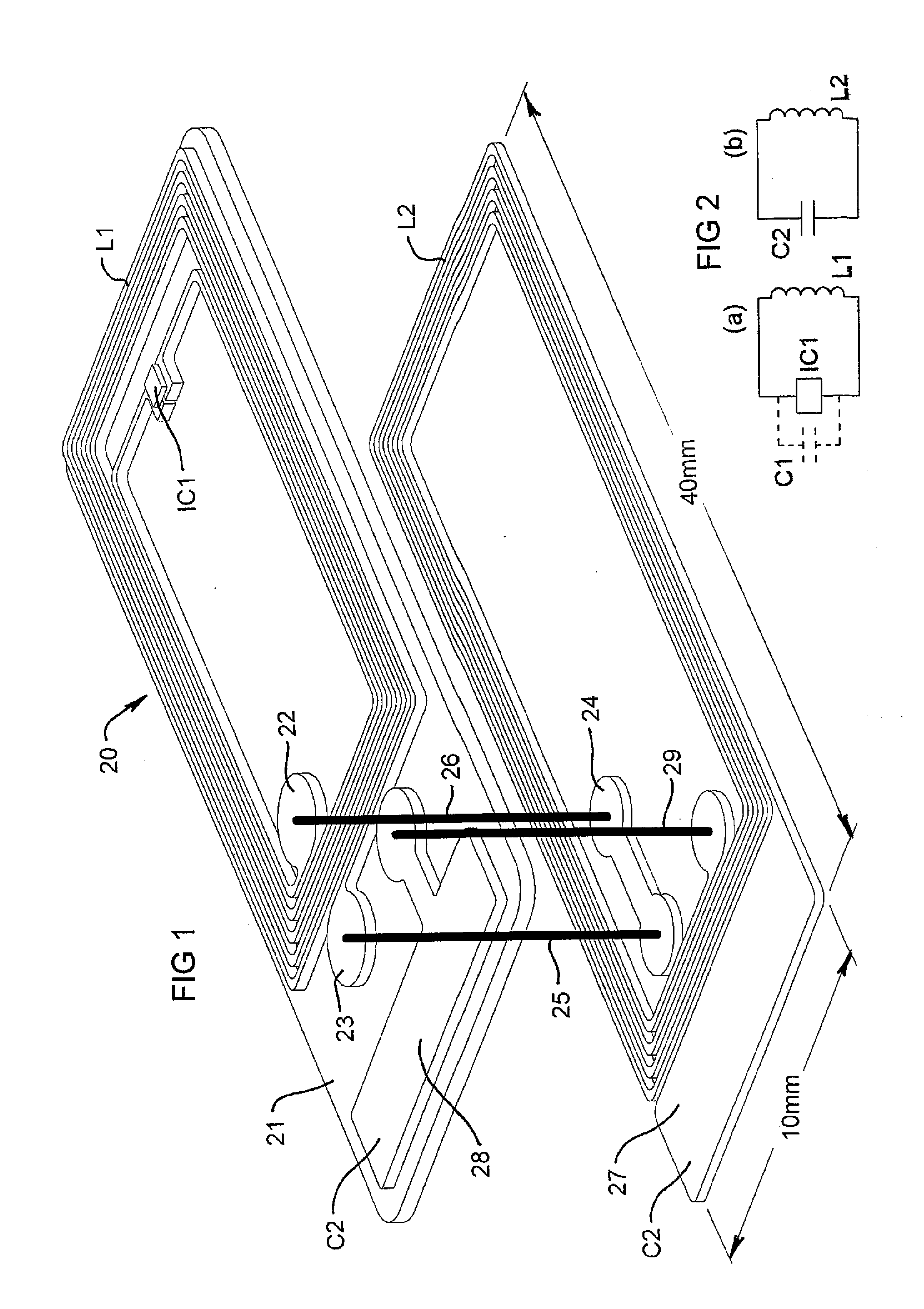
[0030]FIG. 1(a) shows a circuit diagram of a first tuned circuit including a chip associated with a tag according to the present invention;

[0031]FIG. 1(b) shows a circuit diagram of a second tuned circuit associated with the tag;

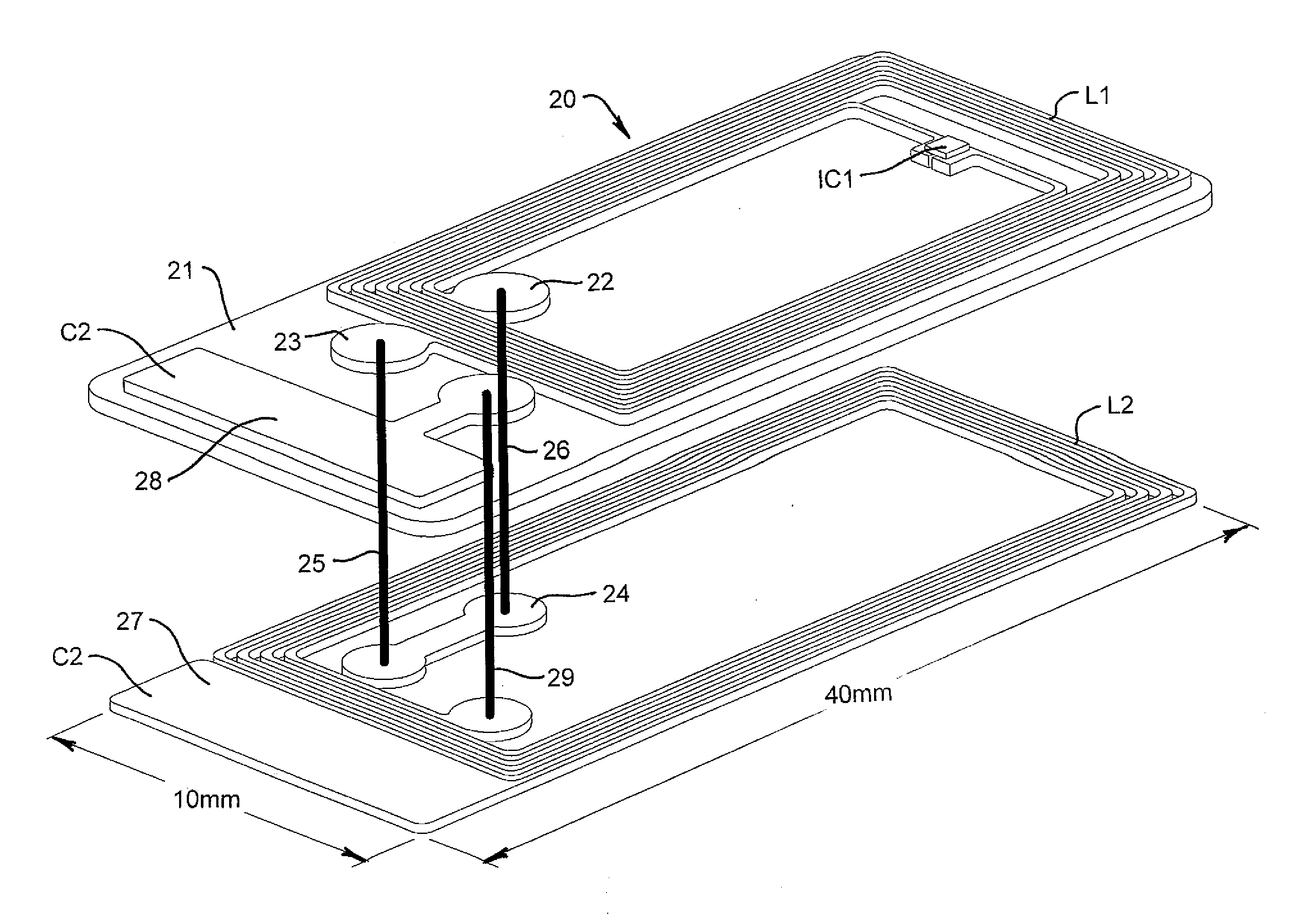
[0032]FIG. 2 shows an exploded view of a tag according to one embodiment of the present invention;

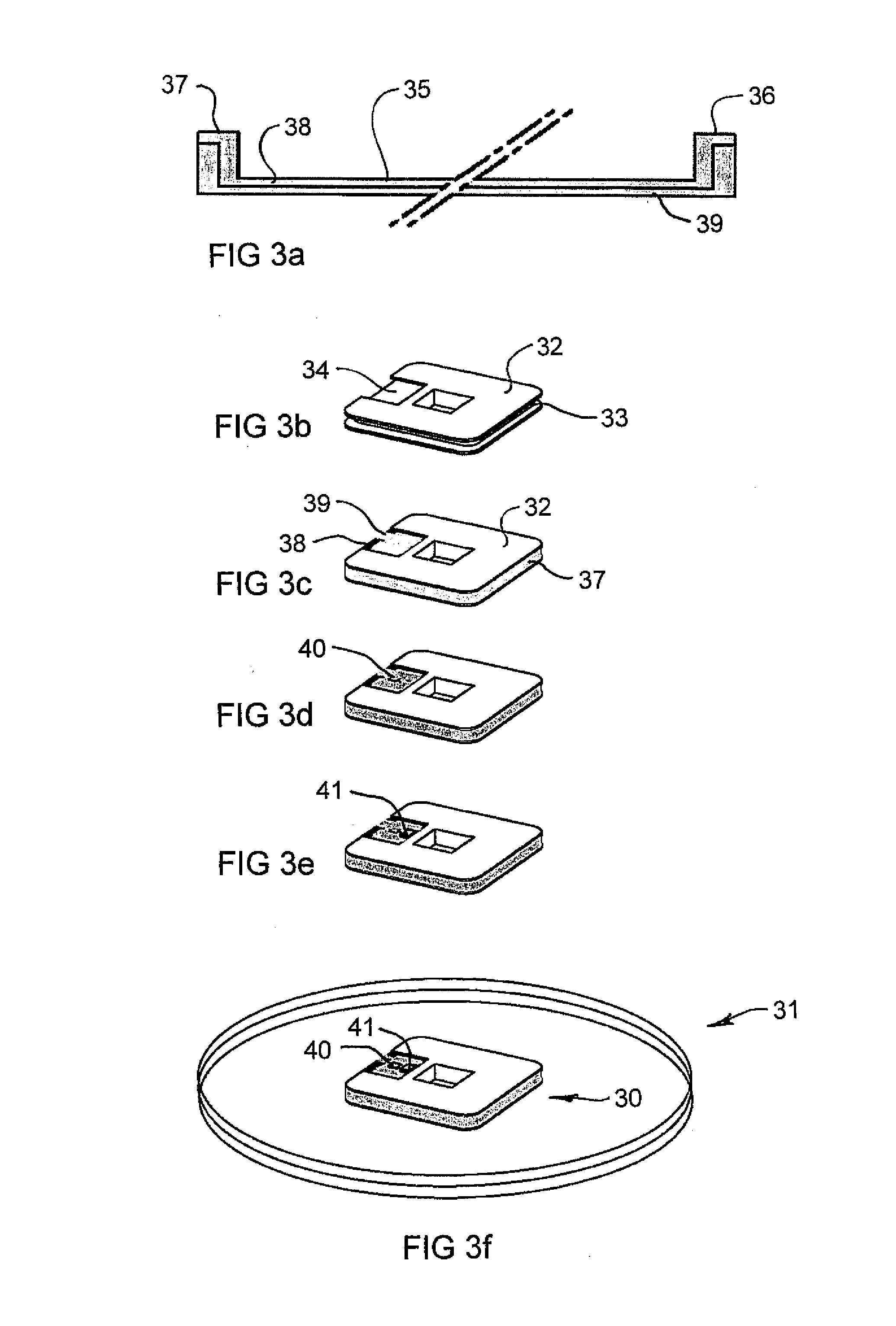
[0033]FIGS. 3(a) to 3(f) show components associated with a tag according to a further embodiment of the present invention.

[0034]FIG. 4 shows the signals from a stack of conventional tags; and

[0035]FIG. 5 shows the signals from a stack of tags according to the present invention.

[0036]FIG. 1(a) shows a first circuit including an inductor L1 and an integrated circuit chip IC1 which contains data and / or identity information together with circuitry for support functions such as reply generation and power supply. Chip IC1 includes an on board...


PUM


Abstract

An RFID tag is disclosed adapted to be read by an interrogator including a reader antenna having a carrier frequency. The tag includes a first circuit including a first inductor and a first capacitor, wherein the first circuit is tuned to a frequency above the carrier frequency to compensate for detuning in the presence of a plurality of tags. The RFID tag includes a second circuit including a second inductor and a second capacitor wherein the first and second inductors are arranged to be coupled electromagnetically with a coupling factor less than unity and the second circuit is tuned to increase coupling between the first circuit and the reader antenna. A method of reading an RFID tag in the presence of a plurality of tags is also disclosed.

Description

FIELD OF THE INVENTION[0001]The present invention relates to a tag for an object management system wherein information bearing electronically coded radio frequency identification (RFID) tags are attached to objects which are to be identified, sorted, controlled and / or audited. In particular the present invention relates to an RFID tag containing two tuned circuits.BACKGROUND OF THE INVENTION[0002]The object management system of the present invention includes information passing between an interrogator or reader which creates an electromagnetic interrogation field, and the electronically coded tags, which respond by issuing a reply signal that is detected by the reader, decoded and consequently supplied to other apparatus in the sorting, controlling or auditing process. The objects to which the tags are attached may be animate or inanimate.[0003]Under normal operation the tags may be passive, i.e. they may have no internal energy source and may obtain energy for their reply from the ...

Claims


Application Information

Patent Timeline
IPC IPC(8): G08B13/14
CPCG06K7/10178G06K19/027G06K19/0726G06K19/07796G06K19/07756G06K19/07767G06K19/07749
Inventor MARTIN, PHILIPPEHALL, DAVID MALCOLM
Owner HID TEXTILE SERVICES SARL
Features
  • R&D
  • Intellectual Property
  • Life Sciences
  • Materials
  • Tech Scout
  • Unparalleled Data Quality
  • Higher Quality Content
  • 60% Fewer Hallucinations
Learn More