Image pickup apparatus

a pickup apparatus and image technology, applied in the field of image pickup apparatus, can solve the problems of reducing the resolution in the traveling direction of the light ray received by each pixel, reducing the image quality of the reproduced image, and difficult to obtain information about the light ray in the desired traveling direction, so as to achieve the effect of increasing the number of pixels in the reproduced image and reducing the image quality

Inactive Publication Date: 2009-01-29
SONY CORP
View PDF15 Cites 115 Cited by
  • Summary
  • Abstract
  • Description
  • Claims
  • Application Information

AI Technical Summary

Benefits of technology

[0012]In the image pickup apparatus according to the embodiment of the invention, an image of an object to be picked up by the image pickup lens section is formed on the microlens array section. Then, a light ray entering into the microlens array section reaches the image pickup device, and is received by a plurality of pixels corresponding to each microlens, and thereby image pickup data including information about the traveling direction of light is obtained. In this case, the aperture stop of the above-described image pickup lens section includes a plurality of aperture sections, thereby a luminous flux is narrowed by each aperture section, and in the image pickup device, light is received in a pixel region corresponding to each aperture section. Therefore, even in the case where the number of microlenses increased to reduce the number of pixels of the image pickup device associated with each microlens, a luminous flux is narrowed by the aperture section in one pixel, and only a light ray of which the traveling direction is limited passes through the aperture section, so compared to a related art in which a single aperture section is arranged in an aperture stop of an image pickup lens, information about a light ray in a desired traveling direction is obtained easily.
[0013]In the image pickup apparatus according to the embodiment of the invention, the aperture stop of the image pickup lens includes a plurality of aperture sections, so even in the case where the number of microlenses increases to reduce the number of pixels associated with each microlens, in the image pickup device, a luminous flux is narrowed by each aperture section to be received, so in a light-sensing region in one pixel, information about a light ray in a desired traveling direction is obtained easily. Therefore, when image processing is performed to obtain a reproduced image, it becomes possible to increase the number of pixels in the reproduced image without a decline in image quality.

Problems solved by technology

However, in the case where the number of pixels associated with each microlens is reduced, the resolution in the traveling direction of a light ray received by each pixel is reduced, and thereby it is difficult to obtain information about a light ray in a desired traveling direction.
Therefore, when the reproduced image is formed by image processing, the image quality of the reproduced image declines.

Method used


Image

  • Image pickup apparatus
  • Image pickup apparatus
  • Image pickup apparatus

Examples


modification 1

[0062]FIGS. 13A and 13B show plan views of color filters 20 and 21 according to a modification 1 of the invention. The color filters 20 and 21 each are arranged on a light-sensing plane of the image pickup device 13 to allow a picked-up color image to be displayed.

[0063]In FIG. 13A, the color filter 20 has a configuration in which each region 12D corresponding to a microlens, that is, each arrangement of 2×2 pixels, is color-coded. Moreover, as a color arrangement, a configuration (arrangement A) in which the ratio of three primary color filters, that is, filters of red (R), green (G) and blue (B), is 1:2:1, and filters of green are regularly arranged on the diagonal is able to be used. In FIG. 13B, the color filter 21 has a configuration in which each pixel P is color-coded, and the same color arrangement (arrangement B) as that of the above-described color filter 20 is used.

[0064]Thus, in the invention, when the color filter in which each predetermined pixel region is color-coded ...

modification 2

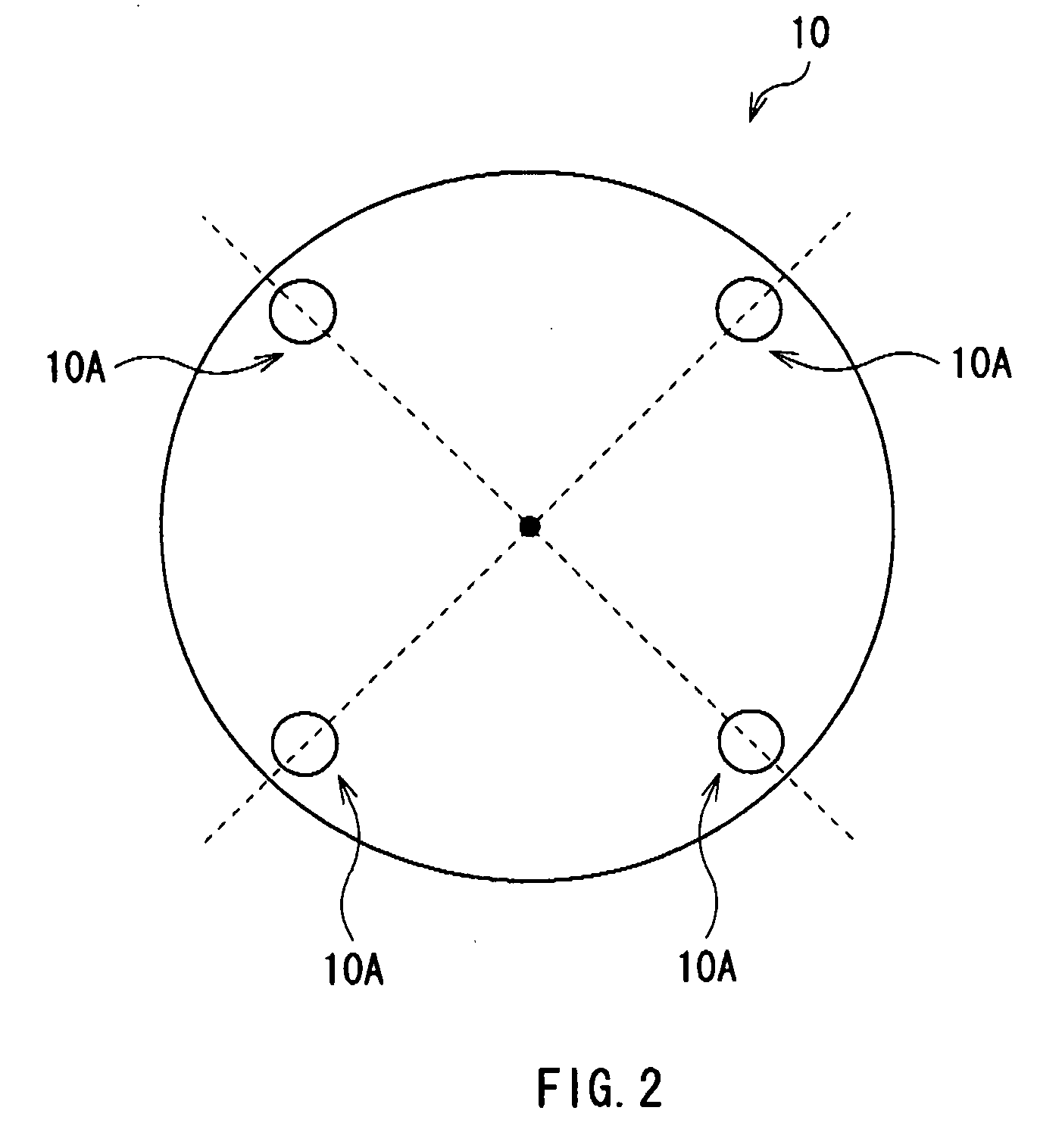
[0065]FIG. 14 shows a schematic plan view of an aperture stop 22 according to a modification 2 of the invention. The aperture stop 22 includes four rectangular aperture sections 22A. Moreover, the aperture sections 22A are rotation-symmetrically arranged with respect to each other on the circumference side of the aperture stop 22. As long as a plurality of aperture sections have the same shape, the shape of the aperture sections is not limited to the above-described circular shape and may have a polygonal shape.

modification 3

[0066]FIG. 15 shows a schematic plan view of an aperture stop 23 according to a modification 3 of the invention. Moreover, FIG. 16 shows a light-sensing region of an image pickup device in the case where the aperture stop 23 is used; and FIGS. 17A and 17B show the configuration of a color filter in the case where the aperture stop 23 is used. The aperture stop 23 includes 8 circular aperture sections 23A. Further, the aperture sections 23A are rotation-symmetrically arranged with respect to each other on the circumference side of the aperture stop 23. Thereby, as shown in FIG. 16, on the image pickup device 13, 8 light-sensing regions 13-2 corresponding to 8 aperture sections 23A are formed in a region where pixels P associated with each microlens are arranged (a reproduction pixel region 25D). Further, the number of pixels P associated with each microlens is 9 (3×3).

[0067]Moreover, in the case where a color image is displayed, as shown in FIG. 17A, a color filter 26 in which each a...


PUM


Abstract

An image pickup apparatus capable of increasing the number of pixels in a reproduced image without a decline in image quality of a picked up image is provided. The image pickup apparatus includes: an image pickup lens section including an aperture stop, the aperture stop including a plurality of aperture sections; an image pickup device obtaining image pickup data on the basis of light received; and a microlens array section being arranged on the focal plane of the image pickup lens section between the image pickup lens and the image pickup device, and including one microlens for a plurality of pixels of the image pickup device.

Description

CROSS REFERENCES TO RELATED APPLICATIONS[0001]The present invention contains subject matter related to Japanese Patent Application JP 2007-184211 filed in the Japanese Patent Office on Jul. 13, 2007, the entire contents of which are incorporated herein by reference.BACKGROUND OF THE INVENTION[0002]1. Field of the Invention[0003]The present invention relates to an image pickup apparatus using a microlens array.[0004]2. Description of the Related Art[0005]Various image pickup apparatuses have been proposed and developed in the past. Moreover, an image pickup apparatus performing predetermined image processing on image pickup data obtained by picking up an image to output the image pickup data has been proposed.[0006]For example, in International Patent Publication No. 06 / 039486 and Ren.Ng, et al. “Light Field Photography with a Hand-Held Plenoptic Camera”, Stanford Tech Report CTSR 2005-02, an image pickup apparatus using a technique called “Light Field Photography” is proposed. The i...

Claims


Application Information

Patent Timeline
Patent Type & Authority Applications(United States)
IPC IPC(8): H04N5/225G02B27/18G03B15/00
CPCH04N5/232H04N5/2254G02B27/0075G02B3/0056H04N23/957H04N23/843H04N25/134
Inventor YAMAMOTO, KENJIYOSHIOKA, SHIGEATSUICHIMURA, ISAO
Owner SONY CORP
Why Eureka
Try Eureka