Overload Relay and Operating Method Thererof

a relay and relay technology, applied in the field of overload relays, can solve the problems of increasing facility costs and significantly reducing work efficiency, and achieve the effect of safe stoppag

Inactive Publication Date: 2009-01-29
MITSUBISHI ELECTRIC CORP
View PDF3 Cites 12 Cited by
  • Summary
  • Abstract
  • Description
  • Claims
  • Application Information

AI Technical Summary

Benefits of technology

[0011]According to the overload relay of the present invention, when a trip-power-source degradation-diagnosing unit determines a degradation of a trip capacitor, the trip-power-source degradation-diagnosing unit forcibly excites a trip coil. Therefore, a trip operation can be securely executed. Further, a load to be protected that is connected to the overload relay can be securely and safely stopped.

Problems solved by technology

However, when this product is used, a power source of a separate system needs to be prepared in addition to a power source system that drives the load, which increases the facility cost.
When an operator performs a recovery operation of a trip-operated overload relay at the site at each time of the trip operation, the work efficiency is significantly reduced.

Method used


Image

  • Overload Relay and Operating Method Thererof
  • Overload Relay and Operating Method Thererof
  • Overload Relay and Operating Method Thererof

Examples


first embodiment

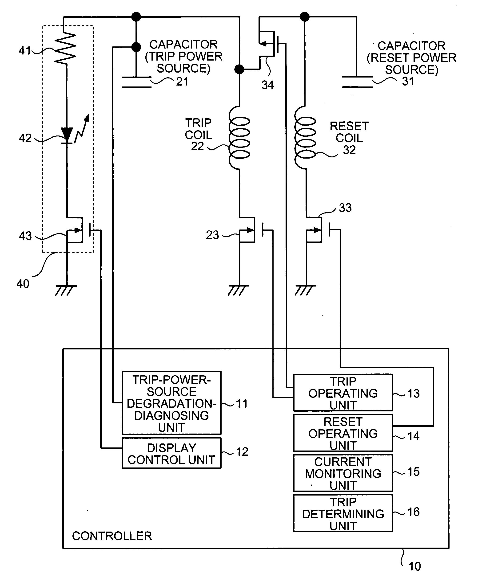
[0033]FIG. 1 is a configuration diagram of an overload relay according to a first embodiment of the present invention. The overload relay shown in FIG. 1 includes a controller 10 that is incorporated in the overload relay and that controls the entire operation of the overload relay. The overload relay also includes capacitors 21 and 31, a trip coil 22, a reset coil 32, switching elements 23, 33, 34, and 43, a resistor element 41, and a light-emitting diode (hereinafter, LED) 42, that are controlled by the controller 10. The capacitor 21 operates as a trip power source for operating the trip coil 22. Similarly, the capacitor 31 operates as a reset power source for operating the reset coil 32. A series circuit of the resistor element 41, the LED 42, and the switching element 43 functions as a display unit 40 that displays a degradation state of the capacitor 21 as described later.

[0034]As shown in FIG. 1, the controller 10 includes a trip-power-source degradation-diagnosing unit 11, a...

second embodiment

[0054]FIG. 4 is a configuration diagram of an overload relay according to a second embodiment of the present invention. The overload relay according to the first embodiment shown in FIG. 1 includes the trip coil 22 and the reset coil 32 separately. However, in the configuration shown in FIG. 4, a trip reset coil 51 serves as both the trip coil and the reset coil as one coil.

[0055]In the above configuration, the drain of the switching element 33 connected to the other end of the reset coil 32 is connected to one end of the trip reset coil 51, and, the drain of the switching element 23 connected to the other end of the trip coil 22 is connected to the other end of the trip reset coil 51. New switching elements 52 and 53 are added. A source of the switching element 52 is connected to one end of the capacitor 21 (the trip power source), and a drain of the switching element 52 is connected to one end of the trip reset coil 51. At the same time, a source of the switching element 53 is con...


PUM


Abstract

An overload relay, which trips a current flow between a power source and a load, includes a trip capacitor that stores therein an electric charge to excite a trip coil so as to trip the current flow, a reset capacitor that stores therein an electric charge to excite a reset coil so as to reset the tripped current flow, an energizing unit that energizes the coils, and a capacitor-diagnosing unit that diagnoses the capacitors. The energizing unit forcibly energizes the trip coil by using the trip charge when the capacitor-diagnosing unit diagnoses that there is a degradation of a property of the trip capacitor.

Description

TECHNICAL FIELD[0001]The present invention relates to an overload relay, and, more specifically to a self-feeding-type overload relay that detects a load current with a current detector such as a CT (Current Transformer) and a hall element and that self-supplies an operation power, and a method of operating the overload relay.BACKGROUND ART[0002]An overload relay is an electric switch that is generally used in a field of industrial machines and industrial facilities, as a unit that protects electric devices (such as a motor, hereinafter, “load”) from damage generated due to overheating or an excessive current. This overload relay is generally used as an electromagnetic switch which is combined with a separate relay called an electromagnetic contactor having no current detecting function. This electromagnetic switch is inserted into a current path that connects between a power source and the load, thereby protecting the load to be protected. In other words, when the overload relay de...

Claims


Application Information

Patent Timeline
Patent Type & Authority Applications(United States)
IPC IPC(8): H02H3/00
CPCH01H71/123H02H3/05H02H1/06
Inventor KAMIYAMA, TOMOYUKISEKIGUCHI, TSUYOSHI
Owner MITSUBISHI ELECTRIC CORP
Why Eureka
Try Eureka