Current Zero Cross Switching Relay Module Using A Voltage Monitor

a voltage monitor and relay technology, applied in relays, emergency protective circuit arrangements, emergency protection arrangements for limiting excess voltage/current, etc., can solve problems such as irregular or complicated ac waveforms, difficulty in precisely timing the actual opening or closing of electrodes, and delay in issuance of close commands. to achieve the effect of facilitating analysis by the processor

Active Publication Date: 2009-01-29
LEGRAND HOME SYST
View PDF81 Cites 59 Cited by
  • Summary
  • Abstract
  • Description
  • Claims
  • Application Information

AI Technical Summary

Benefits of technology

[0017]According to the present disclosure, a novel correlation technique is used to determine the relay open time such that switching corresponds with the current zero-cross. In general, when current is interrupted to an inductive load the magnetic field of the load will cause the voltage on the load side of the relay to spike until an arc is formed whereby the energy in the load's magnetic field is dissipated. This sudden change of voltage is sometimes referred to as inductive kickback. In exemplary embodiments of the present disclosure, a processor analyzes the inductive kickback effect to the load voltage signal in order to dynamically adjust relay open times such that inductive kickback is minimized. Thus, the processor analyzes the load voltage signal data, e.g., for time subsequent to the last line voltage zero cross, amplitude, etc., and the processor also adjusts the relay open time such that the next relay open more accurately approximates relay switching at a zero current point. Each time the relay is opened the resulting kickback is analyzed and the timing is adjusted. By checking the inductive kickback each time the relay is opened the circuit can dynamically adjust for changes in the operation of the relay and load. In general, minimal inductive kickback indicates that the relay open time is optimally configured to correspond with current zero cross. As such, a complex and / or expensive current monitor is not necessary since inductive kickback can be monitored and measured using a voltage monitor, thereby providing a significant commercial advantage as a result.

Problems solved by technology

Since the actuation of a relay requires the physical movement of one of the contact electrodes, there may be some delay from the issuance of a close command until the magnetic field has build to a sufficient level to begin movement of the contact electrodes by overcoming the spring force.
This delay makes it difficult to precisely time the actual opening or closing of the electrodes.
Some AC waveforms are irregular or complicated.
These arcs may cause pits and welds to accumulate on the contact surface which diminish the useful life of the relay.
The extreme heat may also weld the contacts together, thereby making the relay unusable.
In addition, these arcs may cause a build up of carbon deposit on the contacts, which, over time, accumulate to form a high resistance contact between the contacts, thus reducing the current flow to the load and making the relay less efficient.
Unfortunately, these triacs provide a path bypassing the high level of isolation offered by electromechanical relays.
A complicating factor, however, is that in AC circuits, inductors and capacitors generally introduce phase shifts between voltage and current across a given component.
In such instances, opening the relay at a zero voltage would not effectively prevent arcing.
Furthermore, other methods of determining current zero cross generally involve using an expensive current transformer with associated circuitry in order to dynamically measure the load current for a relay.
The use of such current monitors, however, is generally both complicated and expensive.

Method used


Image

  • Current Zero Cross Switching Relay Module Using A Voltage Monitor
  • Current Zero Cross Switching Relay Module Using A Voltage Monitor
  • Current Zero Cross Switching Relay Module Using A Voltage Monitor

Examples


Embodiment Construction

)

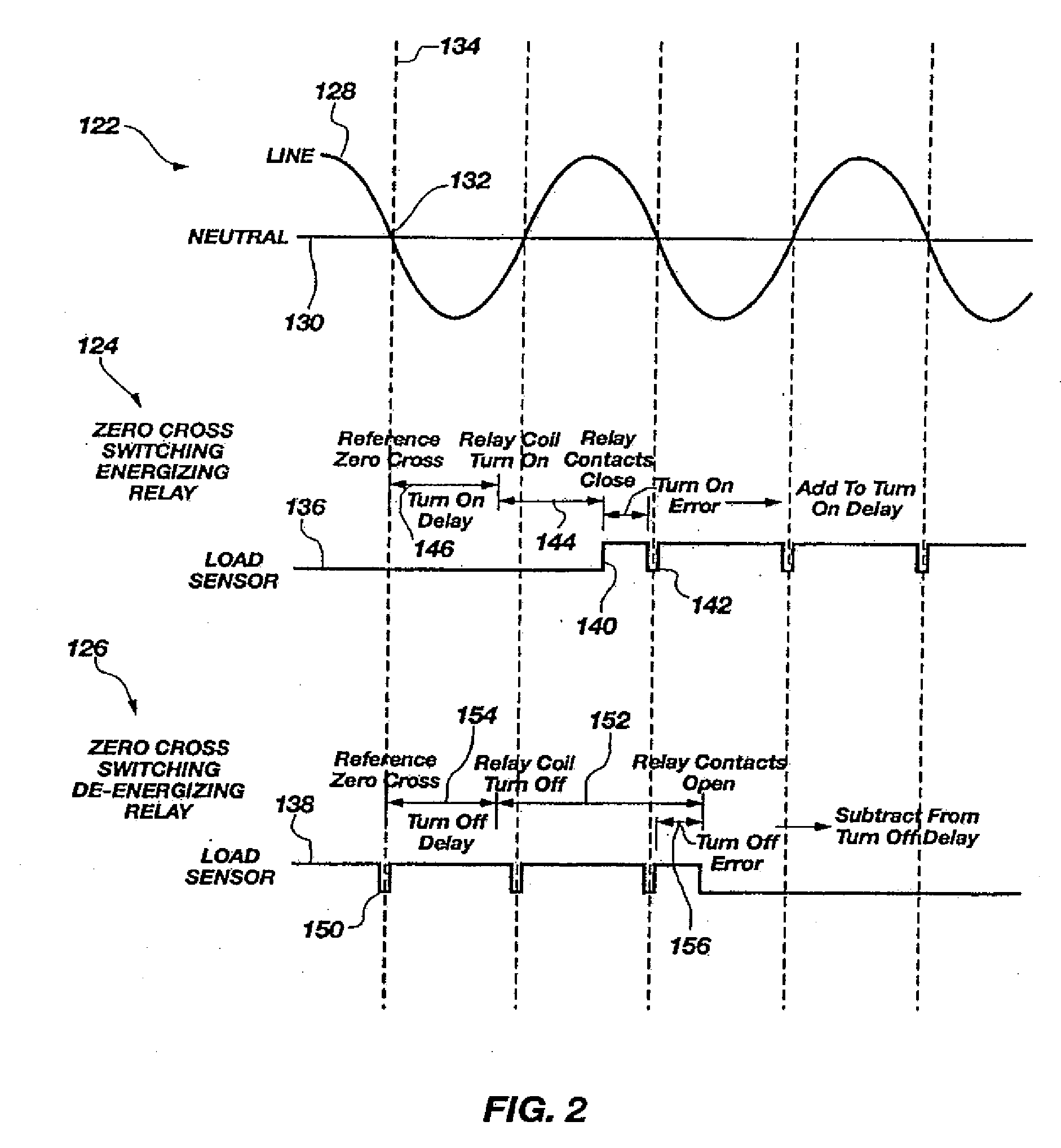
[0026]According to the present disclosure, advantageous assemblies, systems, and methods are provided for dynamically adjusting switching times in order to reduce arcing. More particularly, the disclosed assemblies, systems, and methods generally involve monitoring component waveforms, e.g., voltage on the load side of a relay, and opening / closing the relay at or near a zero crossing, e.g., zero current. In general, dynamic readings of prior actuations are used to anticipate the actuation time for each subsequent operation of the relay. In exemplary embodiments, the dynamic readings are continuously updated each time the relay is actuated to thereby optimize the characteristic switching time for each individual relay and adjust for any variations in switching time over the life of the relay.

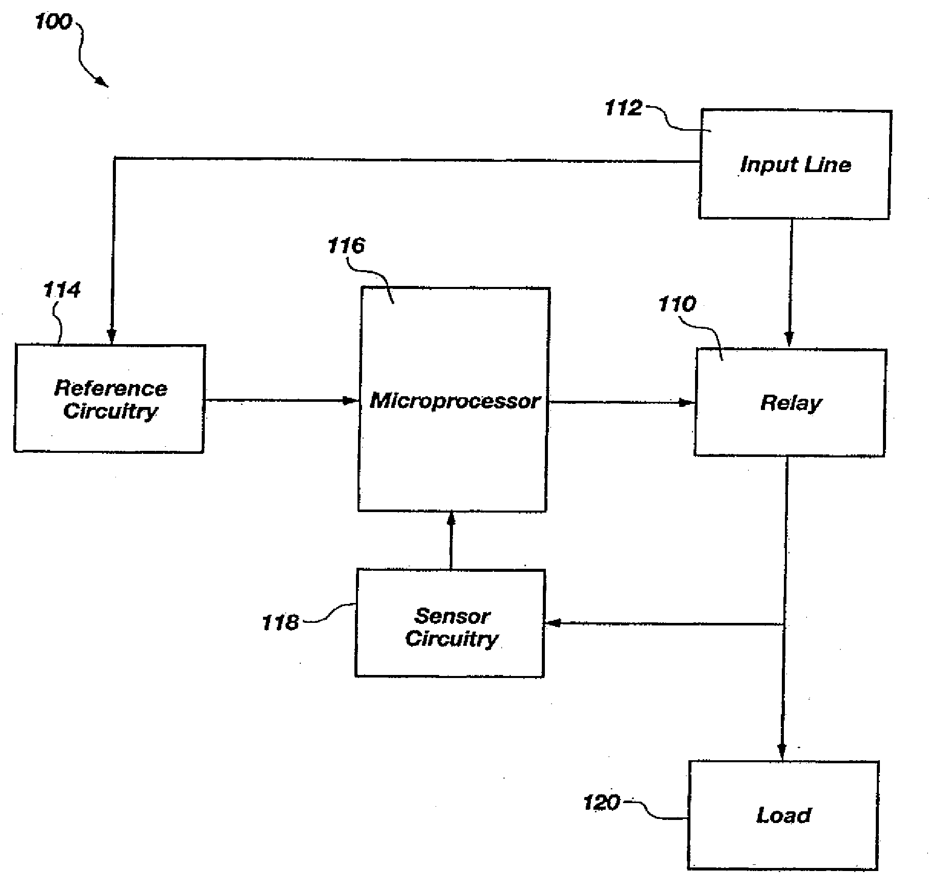
[0027]Referring now to FIG. 1 there is shown generally an exemplary system 100 for zero cross switching in block diagram format. The system 100 typically comprises a relay 110, an input line 112...


PUM


Abstract

Assemblies, systems, and methods which prolong relay life by dynamically compensating the make and break contact timing between the contact points of the relay and a zero crossing point of the power supply's waveform are provided according to the present disclosure. The life cycle of the relay components are dramatically increased through the use of these assemblies, systems, and methods due to a decrease in arcing and other physically damaging phenomena between the contacts of the relay. The present disclosure also provides for assemblies, systems, and methods whereby a processor analyzes the inductive kickback effect in the relay load voltage signal and dynamically adjust the relay open time such that the inductive kickback effect is minimized. In exemplary embodiments, the systems / methods provided herein advantageously adjust the relay open time such that the relay switching time corresponds with current zero cross and do so without requiring complicated current monitoring components.

Description

CROSS-REFERENCE TO RELATED APPLICATIONS[0001]The present application is a continuation-in-part of and claims priority to co-pending U.S. patent application Ser. No. 10 / 934,776 filed Sep. 3, 2004, entitled “Zero Cross Switching Relay Module,” which claims priority to provisional application Ser. No. 60 / 500,147, filed Sep. 3, 2003, both of which are hereby incorporated in their entireties, including but not limited to those portions that specifically appear hereinafter.BACKGROUND[0002]1. Technical Field[0003]The present disclosure relates generally to electrical relays, and more particularly, but not necessarily entirely, relays that switch at specified instances.[0004]2. Background Art[0005]Relays are used as switches to control power to electrical devices. A relay may be defined as an electromechanical switch operated by a flow of electricity in one circuit and controlling the flow of electricity in another circuit. A relay may consist basically of an electromagnet with a soft iron ...

Claims


Application Information

Patent Timeline
Patent Type & Authority Applications(United States)
IPC IPC(8): H01H47/00
CPCH01H9/56
Inventor ALLEN, DOUGLAS E.SMITH, DAVID
Owner LEGRAND HOME SYST
Why Eureka
Try Eureka