
Balanced magnetic brake assembly for exercise cycling apparatus

Inactive Publication Date: 2009-01-29
ELITE SRL
View PDF4 Cites 6 Cited by
  • Summary
  • Abstract
  • Description
  • Claims
  • Application Information

AI Technical Summary

Benefits of technology

[0007]The object of this invention is to overcome the above drawbacks, by providing a brake assembly for a training roller that is highly efficient and relatively cost-effective.
[0013]As a consequence of the mutual coupling of the magnetic elements, which causes their displacements to be mutually dependent and of substantially equal length, the point of application of the moment of the resistance torque will be substantially fixed and substantially coincident with the point of application of the moment of the driving torque, thereby providing a well-balanced long-life assembly, free of vibration and part misalignment problems.
[0014]Advantageously, the magnetic elements may be reciprocally coupled by a kinematic chain, to make easier the construction of the present invention.

Problems solved by technology

One drawback of this prior art solution is that the disc with the magnetic elements mounted thereon tends with time to produce vibrations of variable intensity, thereby causing malfunctioning and unbalancing of the roller which, in the worst cases, may involve the mechanical collapse of the whole structure.

Method used


Image

  • Balanced magnetic brake assembly for exercise cycling apparatus
  • Balanced magnetic brake assembly for exercise cycling apparatus
  • Balanced magnetic brake assembly for exercise cycling apparatus

Examples


Embodiment Construction

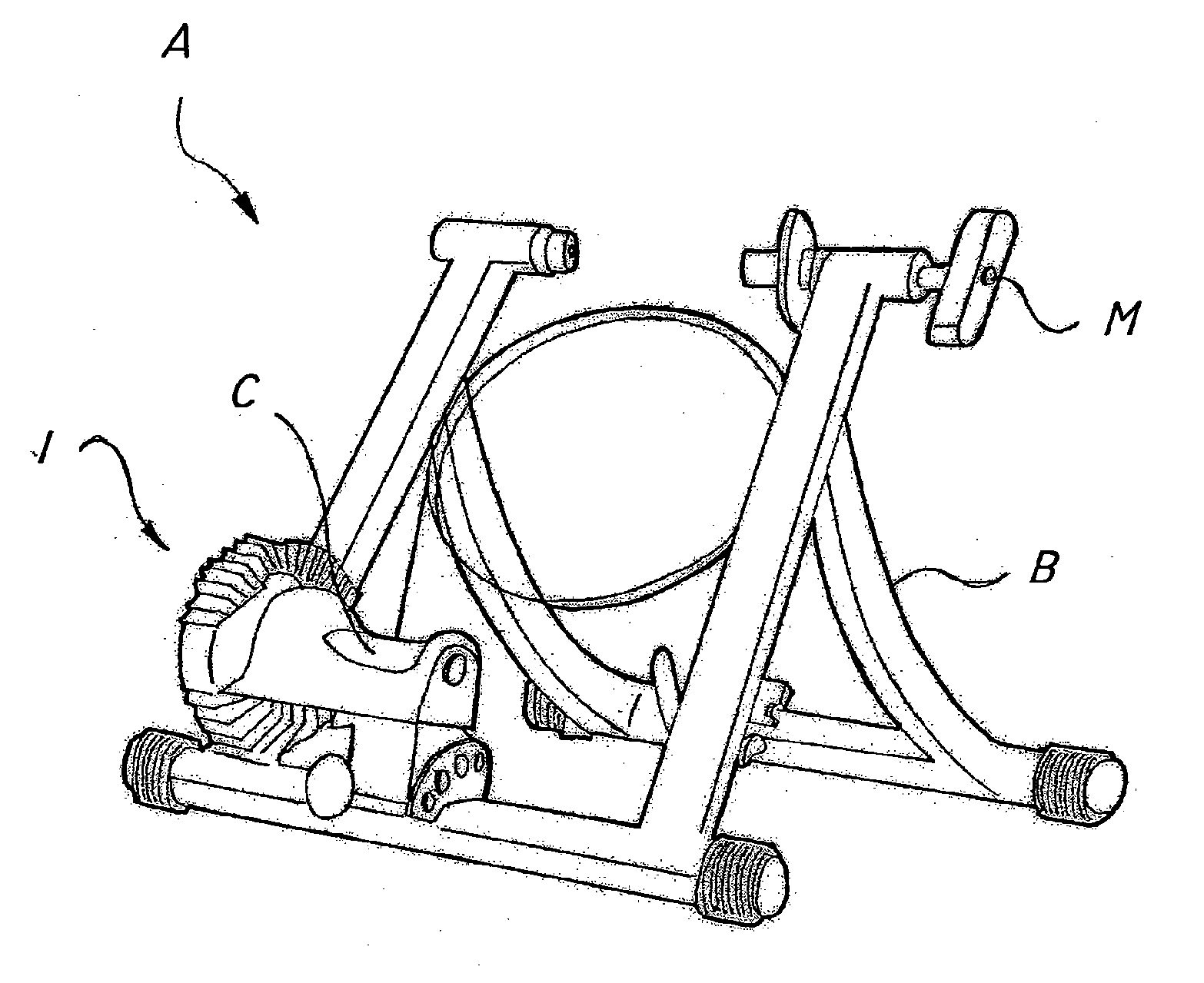
[0029]Referring to the above figures, the brake assembly of the invention, generally designated by numeral 1, will be advantageously fitted, as shown in FIG. 7, to a exercise cycling apparatus A.

[0030]The exercise apparatus comprises a support frame B for the rear wheel of a bicycle, attaching means M for securing the wheel hub to the frame B, a roller C designed to come in contact with the wheel to be rotated by a user through the application of a torque and the brake assembly 1 designed to generate a resistance torque opposing the user-applied driving torque.

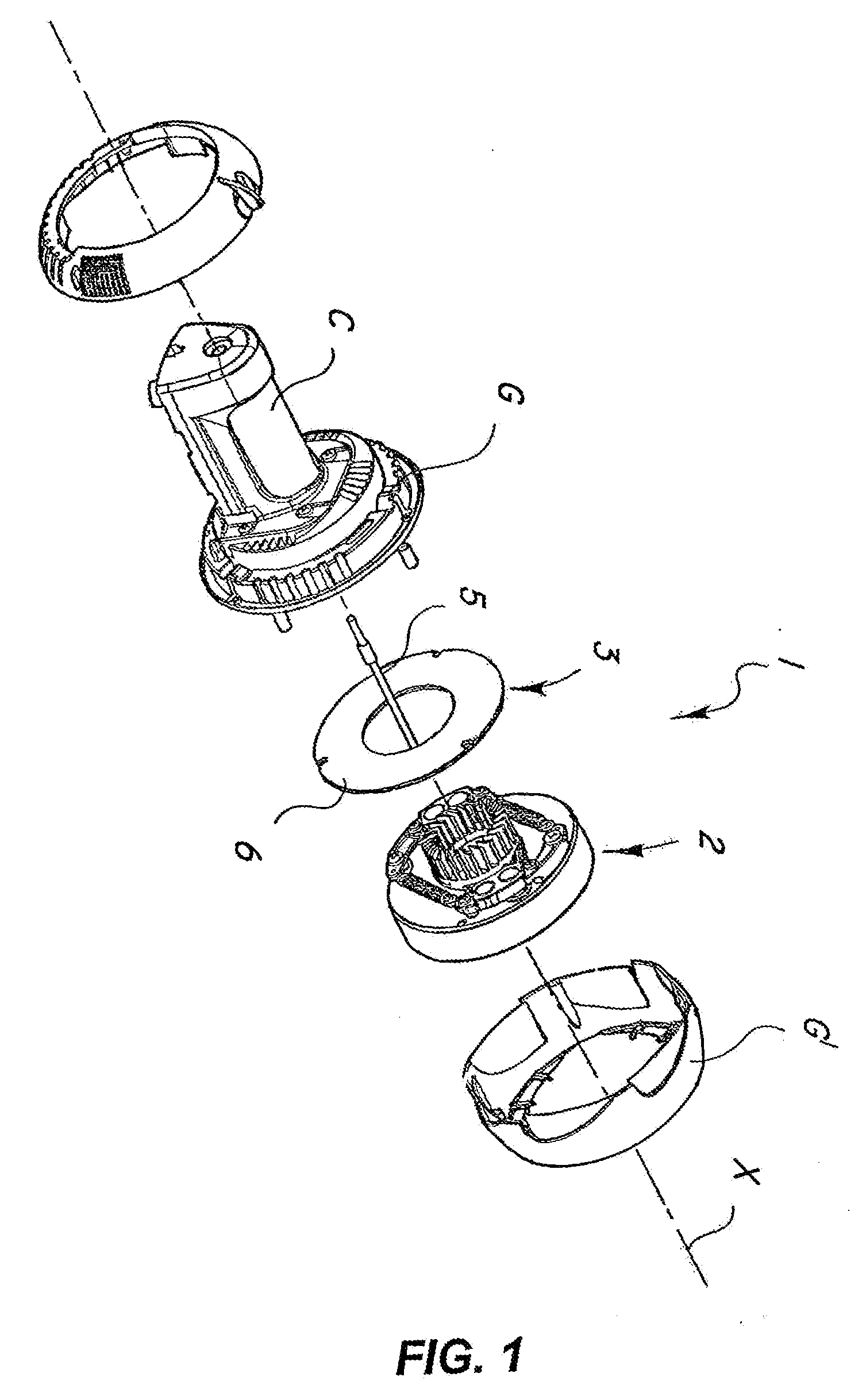
[0031]As shown in FIG. 1, the assembly 1 basically comprises rotor means and stator means, generally designated with numerals 2 and 3 respectively, which are enclosed in two protective casings G and G′, which also contain the roller C.

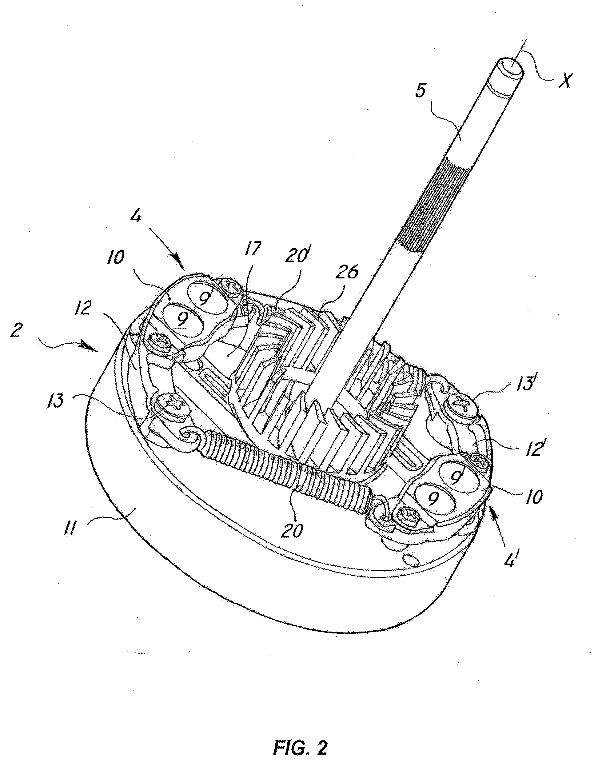
[0032]A pair of magnetic elements 4, 4′ are associated to the rotor means 2, which include a support disc 11, and are designed to be rotated about a longitudinal axis X through the action of a us...


PUM


Abstract

A brake assembly for exercise cycling apparatus comprises rotor means (2) with at least one pair of magnetic elements (4, 4′) adapted to be rotated about a longitudinal axis (X) by a user who applies a driving torque thereon, stator means (3) adapted to cooperate with the at least one pair of magnetic elements (4, 4′) to generate a resistance torque adapted to oppose the above driving torque, guide means (7) associated to the rotor means (2) to cause translation of the magnet elements (4, 4′) along respective directions (d, d′) having at least one radial component to cause variation of the resistance torque proportionally to the driving torque. The magnetic elements (4, 4′) are reciprocally coupled to make the displacement thereof along directions (d, d′) mutually dependent and with substantially the same length (l, l′).

Description

FIELD OF THE INVENTION[0001]The present invention finds application in the field of sport and leisure accessories, and particularly relates to a balanced magnetic brake assembly for exercise cycling apparatus.[0002]The invention further relates to an exercise cycling apparatus incorporating such assembly.BACKGROUND OF THE INVENTION[0003]Exercise cycling apparatus are known which essentially comprise a support frame having a bolt for locking the hub of the rear wheel of a bicycle so that the latter can rotate by contact engagement with a horizontally extending roller by applying a driving torque which is variable according to the pedaling force exerted by the user.[0004]Such roller is braked by a brake assembly suitable to generate a resistance torque opposing the applied driving torque to simulate a more or less difficult route, thereby training the muscular and cardiovascular systems of the user. The resistance torque is typically generated by various types of means: mechanical, hy...

Claims


Application Information

Patent Timeline
IPC IPC(8): A63B22/06
CPCA63B21/0051A63B21/22A63B2069/167A63B2069/164A63B69/16
Inventor SARTORE, ALMERIGO
Owner ELITE SRL
Learn More