Process for the production of interchangeable vacuum test tube holders for taking blood samples and product obtained therefrom

a technology of vacuum test tube and holder, which is applied in the direction of catheters, sensors, infusion needles, etc., can solve the problems of vacuum test tube, very wide angle, inability to take blood samples, etc., and achieve the effect of convenient needle insertion, convenient insertion of holder needles, and no patient discomfort or pain

Inactive Publication Date: 2009-01-29
CASAROTTO ALFONSA +1
View PDF5 Cites 2 Cited by
  • Summary
  • Abstract
  • Description
  • Claims
  • Application Information

AI Technical Summary

Benefits of technology

[0026]A further objective of the new process is to produce a holder with a needle bent at two points without inaccuracies, imperfections, non alignments or incorrect orientation.
[0027]A further objective of the new holder with a needle bent at two points is to facilitate the insertion of the needle into the vein without causing the patient discomfort or pain.
[0028]A further objective of the new holder is to facilitate the insertion of t

Problems solved by technology

Further, the nurse must not insert the needle through the vein, penetrating-the vein from side to side, because this would produce a hematoma in the patient and also because that would make it impossible to take the blood sample.
Said cylinder, which is suited to contain a vacuum test tube, has the disadvantage of being very wide.
During the taking of a blood sample, when the needle extending from the holder is inserted into the patient's vein, the needle penetrates the skin at a very wide angle, because the thickness of the holder makes it impossible to position the needle near the skin in a substantially tangential position.
All of this does not prevent possible perforation of the vein, however.
Furthermore, said contrivances cause discomfort and in some cases even pain to the patient.
Furthermore, butterfly needles are expensive to purchase and dispose of.
Although these holders theoretically enable a better insertion of the needle into the vein, they

Method used


Image

  • Process for the production of interchangeable vacuum test tube holders for taking blood samples and product obtained therefrom
  • Process for the production of interchangeable vacuum test tube holders for taking blood samples and product obtained therefrom
  • Process for the production of interchangeable vacuum test tube holders for taking blood samples and product obtained therefrom

Examples


Embodiment Construction

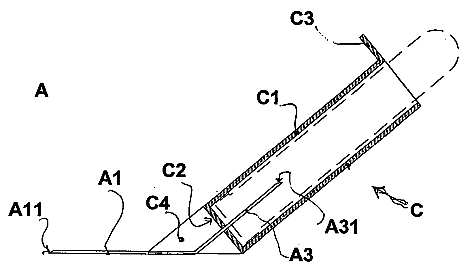
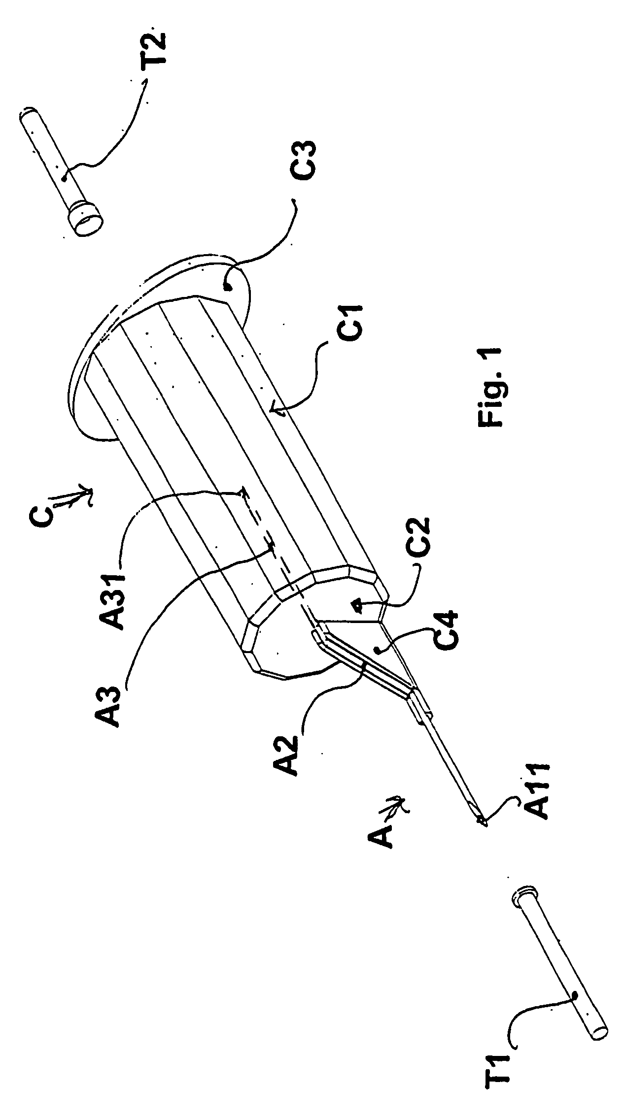
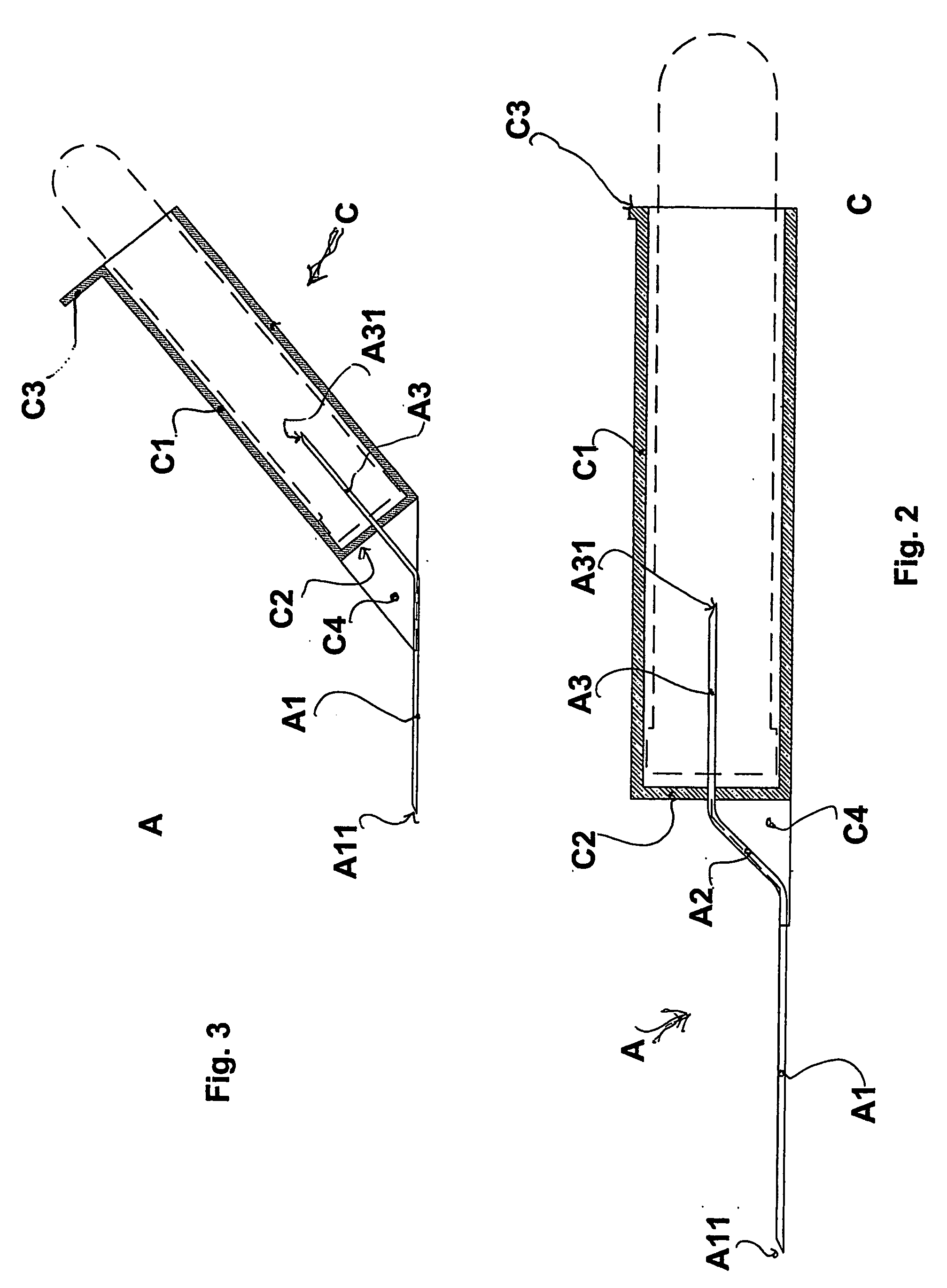
[0042]Turning first to FIGS. 1-2, there is shown a first embodiment of the invention. A shaped needle (A) consists of three consecutive sections (A1, A2, A3), of which the two extreme sections (A1, A3) are parallel and not lying on the same axis. The intermediate section (A2) connects said two extreme sections (A1, A3) and is slanted with respect to each of them.

[0043]Both of said extreme sections (A1, A3) have an angled or slanted tip (A11, A31), in order to facilitate the penetration into the skin and into a vein at one end and the perforation of, and penetration into, the seal cap of a vacuum test tube at the other end.

[0044]The casing (C) consists of a cylinder (C1) closed on the front side (C2) and provided with outer tabs (C3) at the other end.

[0045]On the front closing wall (C2) of the casing (C) the shaped needle (A) is applied, so that an end section (A3) of said needle (A) is positioned inside the casing (C), coaxial with the cylindrical part (C1) of the casing (C).

[0046]T...


PUM

PropertyMeasurementUnit
Coloraaaaaaaaaa

Abstract

A process for the production of a tubular holder for vacuum test tubes and the holder obtained therefrom. The process includes the steps of inserting a straight needle into the holder and the subsequent bending of the needle, so that the outer end of the needle is first connected to the edge of a slanted support wall extending from the casing and has a terminal portion aligned with a side wall of the casing, thus facilitating the insertion of the needle into the limb of a patient. The new disposable holder is particularly useful for blood sampling because it provides for the alignment of the needle with respect to the patient's vein.

Description

BACKGROUND OF THE INVENTION[0001]1. Field of the Invention[0002]The present invention concerns a device for taking blood samples, and, more particularly, a holder provided with a needle, into which holder vacuum test tubes for taking blood samples are inserted, and the process for the production thereof.[0003]2. Description of Related Art[0004]Numerous medical diagnoses require the analysis of blood samples taken directly from a patient's vein.[0005]When blood samples are taken, it is very important to prevent the transmission, both between patients and between patient and nurse, of any diseases, germs, viruses and similar.[0006]Further, the nurse must not insert the needle through the vein, penetrating-the vein from side to side, because this would produce a hematoma in the patient and also because that would make it impossible to take the blood sample.[0007]The syringe, as a means of taking blood samples from a patient, may be replaced with a holder provided with a needle, integra...

Claims


Application Information

Patent Timeline
IPC IPC(8): A61B5/15B23P11/00A61M5/34
CPCA61B5/1438Y10T29/49826A61M2005/342A61B5/15003A61B5/150282A61B5/150297A61B5/150389A61B5/150473A61B5/150526A61B5/150717A61B5/150732A61B5/154A61B5/150786
Inventor CASAROTTO, ALFONSADALL'ARA, CHIARA
Owner CASAROTTO ALFONSA
Why Eureka
Try Eureka