Electronically controlled prosthetic system

a prosthetic system and electric control technology, applied in the field of ankle and foot joint system, can solve the problems of increasing the amount of force required to initiate or sustain movement in the damper, increasing cost and complexity, and increasing the reliance on the user's own muscle strength, so as to improve safety, optimize energy return, and facilitate uneven ground traversal

Inactive Publication Date: 2009-01-29
MARTIN JAMES J
View PDF10 Cites 222 Cited by
  • Summary
  • Abstract
  • Description
  • Claims
  • Application Information

AI Technical Summary

Benefits of technology

[0034]Still yet another object of the present invention is to provide a new and improved prosthetic ankle and foot system that generally utilizes a keel design wherein energy return is optimized and uneven ground is more easily traversed.
[0035]A further object of the present invention is to provide a new and improved prosthetic ankle and foot system for multiple levels of amputation and addresses issues of gait for all activity levels by allowing the foot to dorsiflex through swing phase of gait thus greatly enhancing safety, decreasing mental anxiety, and increasing gait symmetry.
[0036]Still another object of the present invention is to provide a new and improved prosthetic ankle and foot system that provides cosmetic effect through better simulating proper natural human locomotion, allowing the foot to plantar flex during sitting, and features a more cosmetically shaped foot shell which may selectively be chosen from a variety of styles.
[0037]Another object of

Problems solved by technology

In addition, the level of power that the prosthesis may provide may decrease a certain amount over time so that it systematically causes the user to rely more and more on their own muscle strength.
As the valve may tend to close, there may be a larger force required to initiate or sustain movement in the damper.
Because the use of numerous sensors in such a system may add cost and complexity, and lower durability and dependability, it is generall

Method used


Image

  • Electronically controlled prosthetic system
  • Electronically controlled prosthetic system
  • Electronically controlled prosthetic system

Examples


Embodiment Construction

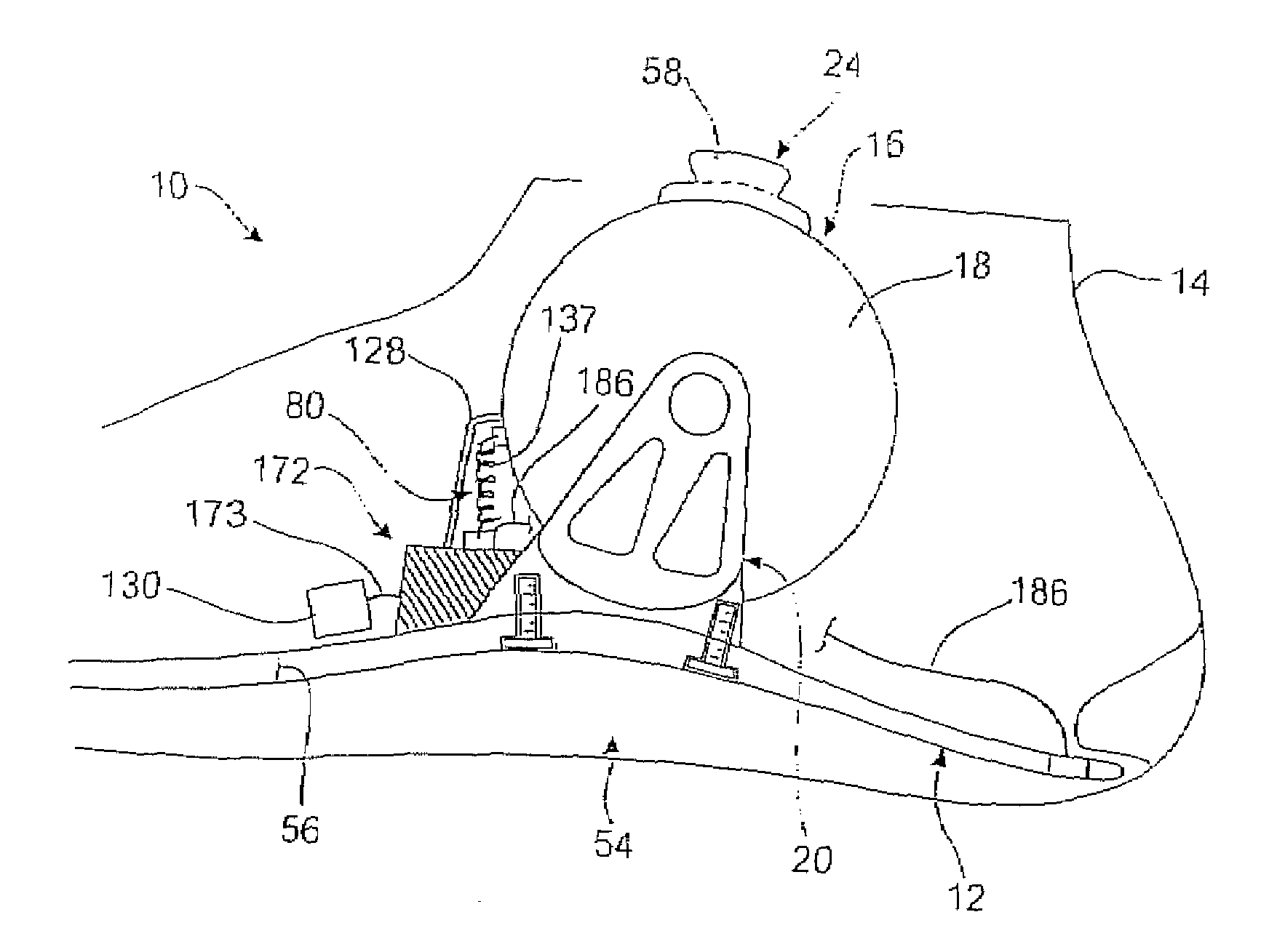
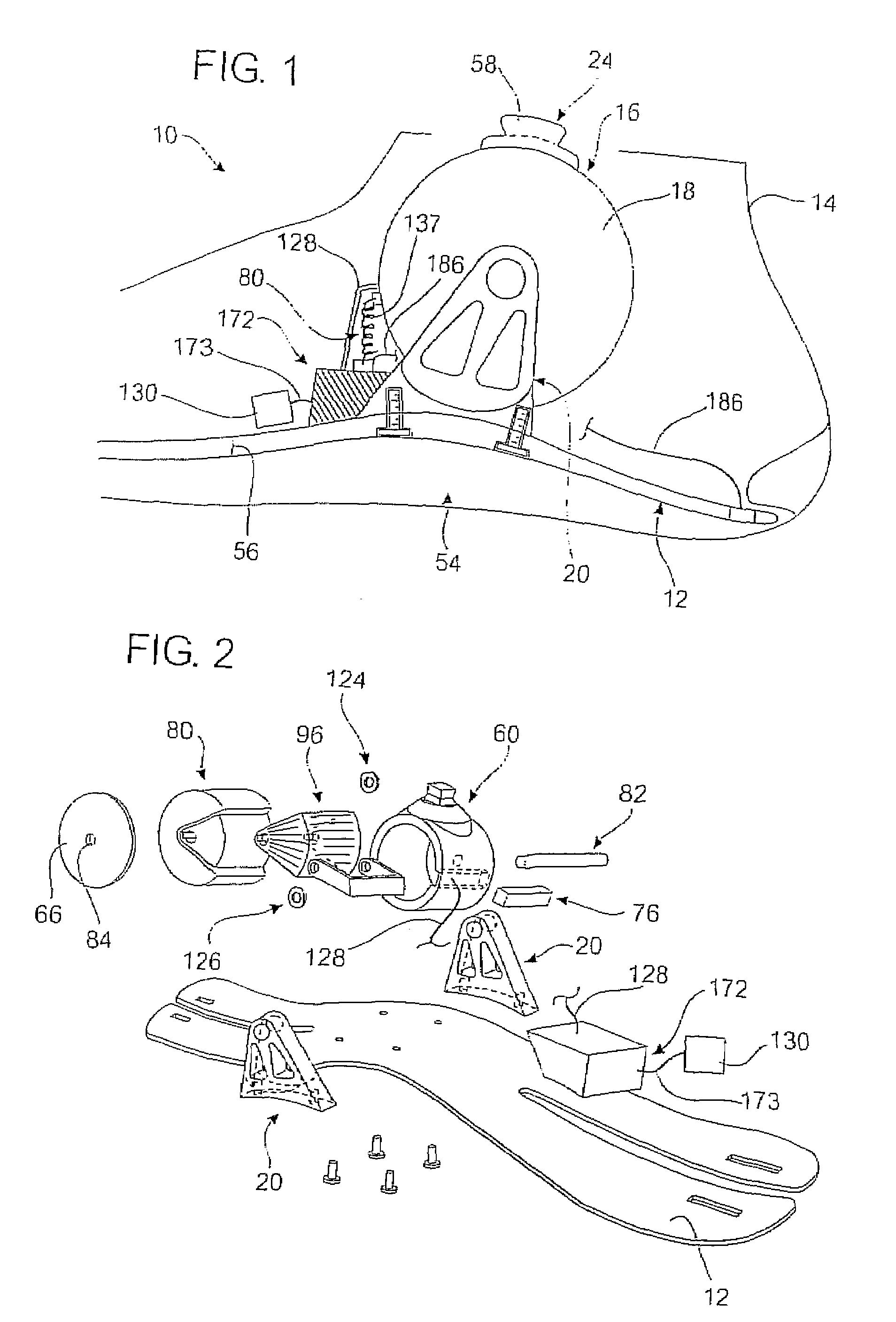
[0116]Referring now to the drawings, wherein like reference numerals designate corresponding structure throughout the views, and referring in particular to FIGS. 1 and 2, reference numeral 10 generally refers to a new and improved prosthetic foot with ankle system, hereinafter referred to as prosthetic foot collectively, in accordance with the present invention. Invention 10 generally comprises keel 12, foot shell 14, ankle joint assembly 16, dampening means or system 18, a bracket assembly 20, sensor system 22, and attachment means 24. It should not be considered limiting what order certain components are depicted in the attached drawings. For instance, attaching either the inner or outer cylinder to the keel should be considered to be within the scope of the same invention, and does not depart from the intended disclosure. It should be understood that there are a number of orientations that various components may be placed to provide a similar benefit to the end user.

[0117]Further...


PUM


Abstract

A prosthetic joint system for users comprising a housing having an interior cavity, a center axis in said interior cavity, and an attachment means for fixedly connecting said housing to said user; an inner cylinder disposed in said housing interior cavity wherein said inner cylinder rotates around said center axis of said housing; an appendage attached to said inner cylinder; a sensor system attached to said appendage; and a dampening system, having a power source, in communication with said sensor system, said inner cylinder, and said housing for controlling dampening of the rotation of said inner cylinder around said center axis of said housing.

Description

CROSS-REFERENCE TO RELATED APPLICATIONS[0001]This application is a continuation-in-part of U.S. patent application Ser. No. 11 / 953,390 filed Dec. 10, 2007, which is a continuation of U.S. patent application Ser. No. 11 / 801,790 filed May 11, 2007, which is a continuation-in-part of U.S. patent application Ser. No. 11 / 343,066 filed Jan. 30, 2006, which is a continuation of U.S. Pat. No. 7,029,500 filed Apr. 9, 2003 and issued on Apr. 18, 2006.FIELD OF THE INVENTION[0002]The present invention relates generally to an ankle and foot joint system. More particularly, the present invention is a new and improved prosthetic joint system which simulates natural human locomotion and human biomechanics through sensory feedback, time feedback, electronically controlled dampening joint assembly, and a microprocessor control system.BACKGROUND OF THE INVENTION[0003]As the study of human physiology and anatomy clearly demonstrates, the relative simple action of walking on an even flat surface involve...

Claims


Application Information

Patent Timeline
IPC IPC(8): A61F2/66
CPCA61F2/581A61B5/4851A61F2/605A61F2/64A61F2/6607A61F2/68A61F2/72A61F2002/5004A61F2002/5006A61F2002/5018A61F2002/5033A61F2002/5035A61F2002/5049A61F2002/6621A61F2002/6642A61F2002/6685A61F2002/6818A61F2002/6827A61F2002/701A61F2002/704A61F2002/705A61F2002/745A61F2002/7625A61F2002/7635A61F2002/764A61F2002/7645A61F2002/7665A61F2002/769A61B5/112A61F2/582A61F2/70A61F2/74
Inventor MARTIN, JAMES J.
Owner MARTIN JAMES J
Why Eureka
Try Eureka