Apparatus and method for fast one-to-many microcode patch

a microprocessor and one-to-many technology, applied in the field of microelectronics, can solve the problems of two-cycle pipeline bubble, complex sequence of micro instructions stored in the microcode rom, and easy errors of micro code patches,

Inactive Publication Date: 2009-01-29
VIA TECH INC
View PDF0 Cites 25 Cited by
  • Summary
  • Abstract
  • Description
  • Claims
  • Application Information

AI Technical Summary

Benefits of technology

[0019]Another aspect of the present invention comprehends a method for performing a one-to-many microcode patch corresponding to a micro instruction stored in microcode ROM. The method includes: within a translate stage of a microprocessor, concurrently providing a microcode ROM address to a microcode ROM and to a patch array; determining that the microcode ROM address matches one of a plurality of entries within the patch array, outputting a corresponding branch instruction, and asserting a hit signal, where the branch instruction prescribes a branch target address; responsive to assertion of the hit signal, routing the corresponding branch instruction to an instruction register for execution; branching to a location in a microcode RAM that corresponds to the branch target address, and subsequently executing one or more patch instructions which are stored at the location in the microcode RAM.

Problems solved by technology

As one skilled in the art will appreciate, it is the complex sequences of micro instructions that are stored in the microcode ROM which are more prone to error.
But in practice, providing mechanisms for microcode patches is very complex because of a requirement that the throughput of a part not be disadvantageous affected in its operating environment.
McGrath et al. further note that while this approach is advantageous, it is also limiting in that switching control from the microcode ROM to the RAM causes a two-cycle bubble in the pipeline.
That is, microcode patches according to the technique disclosed by McGrath et al. are provided at the cost of performance and throughput.

Method used


Image

  • Apparatus and method for fast one-to-many microcode patch
  • Apparatus and method for fast one-to-many microcode patch
  • Apparatus and method for fast one-to-many microcode patch

Examples


Embodiment Construction

[0030]The following description is presented to enable one of ordinary skill in the art to make and use the present invention as provided within the context of a particular application and its requirements. Various modifications to the preferred embodiment will, however, be apparent to one skilled in the art, and the general principles defined herein may be applied to other embodiments. Therefore, the present invention is not intended to be limited to the particular embodiments shown and described herein, but is to be accorded the widest scope consistent with the principles and novel features herein disclosed.

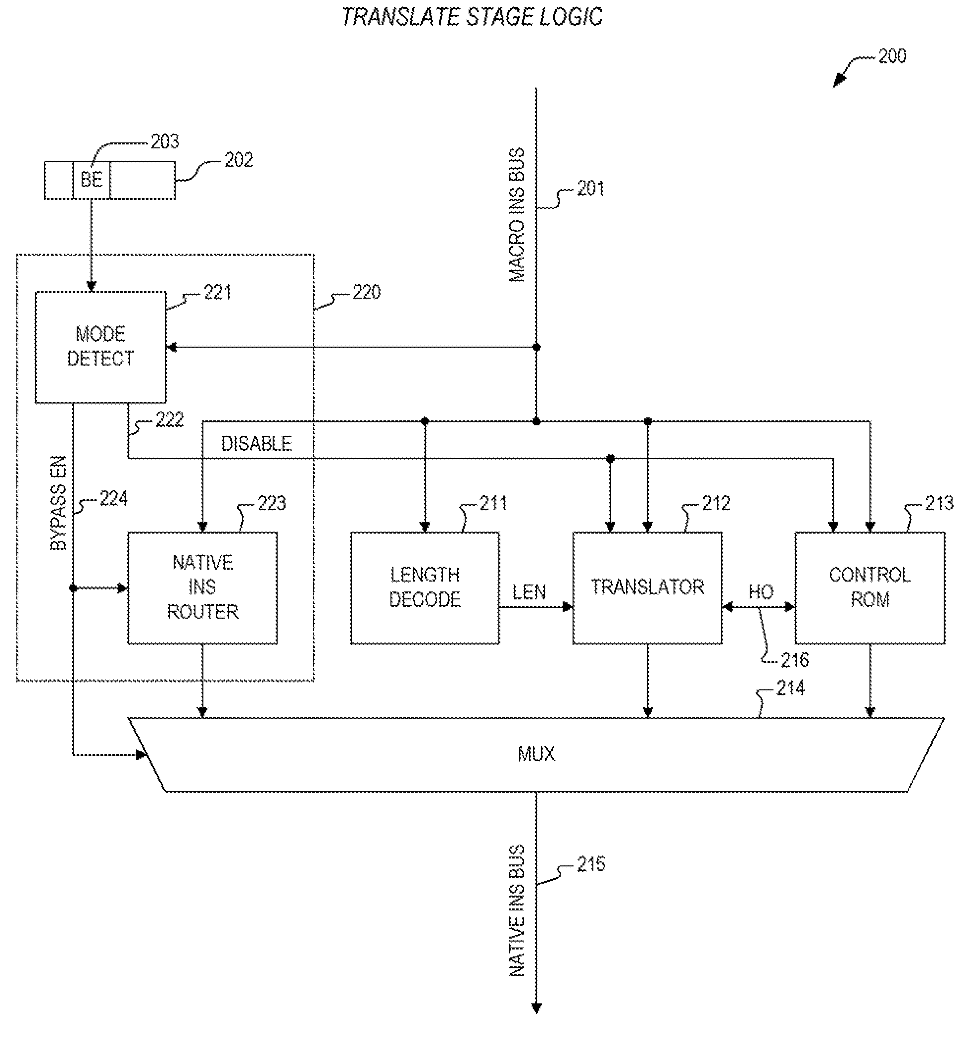
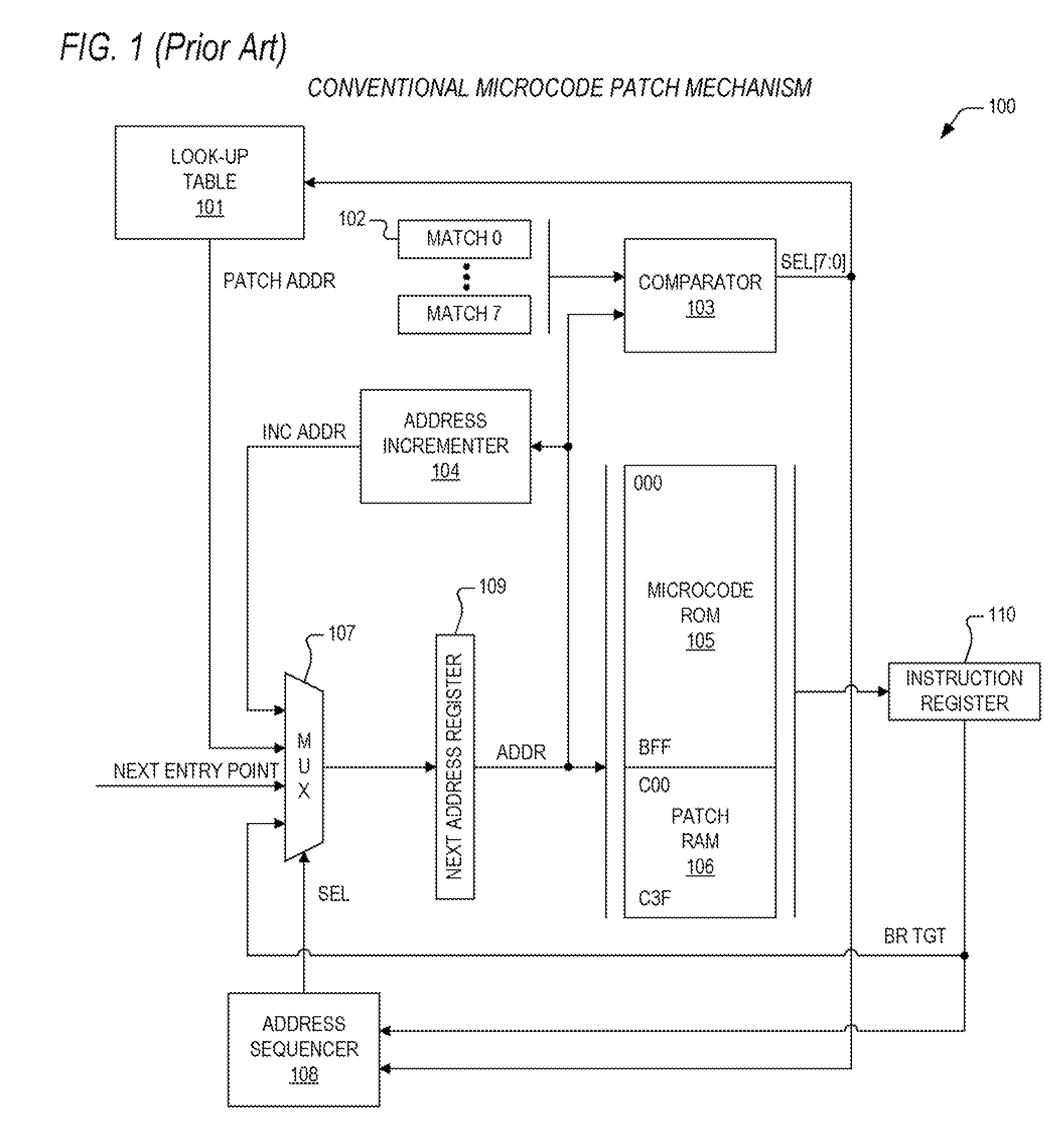
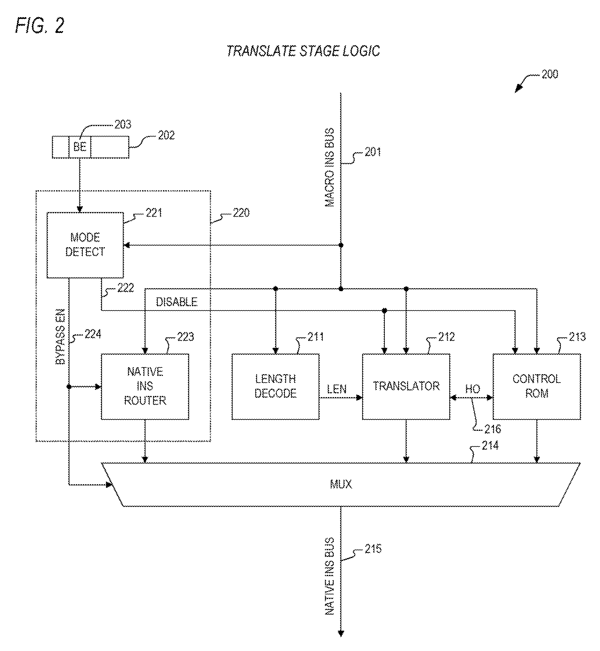
[0031]In view of the above background discussion on mechanisms for making microcode patches within a present day microprocessor, a discussion highlighting the limitations of these mechanisms will be provided with reference to FIG. 1. Following this, a discussion of the present invention will be presented with reference to FIGS. 2-9. The present invention provides a flexible and...


PUM


Abstract

A microcode patch apparatus including a patch array, a mux, and a RAM. The patch array receives a microcode ROM address and determines that the microcode ROM address matches one of a plurality of entries within the patch array. The patch array outputs a corresponding branch instruction and asserts a hit signal. The branch instruction prescribes a microcode branch target address. The mux receives the branch instruction from the patch array and a micro instruction corresponding to the microcode ROM address from a microcode ROM. The mux provides the micro instruction or the corresponding branch instruction to an instruction register based upon the state of the hit signal. The RAM stores a plurality of patch instructions that are to be executed in place of the micro instruction. The first one of the plurality of patch instructions is stored at a location in the RAM corresponding to the microcode branch target address.

Description

CROSS-REFERENCE TO RELATED APPLICATIONS[0001]This application is related to the following co-pending U.S. patent applications, each of which has a common assignee and common inventors.SERIALFILINGNUMBERDATETITLE                  Jul. 24, 2007APPARATUS AND METHOD FOR(CNTR.2292)REAL-TIME MICROCODE PATCH                  Jul. 24, 2007APPARATUS AND METHOD FOR(CNTR.2408)FAST MICROCODE PATCHFROM MEMORY                  Jul. 24, 2007MICROCODE PATCH EXPANSION(CNTR.2409)MECHANISM                  Jul. 24, 2007ON-CHIP MEMORY PROVIDING FOR(CNTR.2410)MICROCODE PATCH OVERLAY ANDCONSTANT UPDATE FUNCTIONS                  Jul. 24, 2007MECHANISM FOR IMPLEMENTING A(CNTR.2411)MICROCODE PATCH DUIRNGFABRICATION                  Jul. 24, 2007CONFIGURABLE FUSE MECHANISM(CNTR.2412)FOR IMPLEMENTING MICROCODEPATCHESBACKGROUND OF THE INVENTION[0002]1. Field of the Invention[0003]This invention relates in general to the field of microelectronics, and more particularly to an apparatus and method for performing...

Claims


Application Information

Patent Timeline
Patent Type & Authority Applications(United States)
IPC IPC(8): G06F13/00
CPCG06F8/66G06F9/30145G06F9/268
Inventor HENRY, G. GLENNPARKS, TERRY
Owner VIA TECH INC
Why Eureka
Try Eureka