Suction port assembly of vacuum cleaner

a vacuum cleaner and suction port technology, applied in the field of vacuum cleaners, can solve the problems of user inconvenience, increased complexity of the structure, and drawbacks of the convertible vacuum cleaner, and achieve the effects of reducing the overall height, simple and fast conversion between upright and canister modes, and simple structur

Inactive Publication Date: 2009-02-05
SAMSUNG GWANGJU ELECTRONICS CO LTD
View PDF5 Cites 59 Cited by
  • Summary
  • Abstract
  • Description
  • Claims
  • Application Information

AI Technical Summary

Benefits of technology

[0021]Accordingly, a convertible vacuum cleaner which has a simple structure can be provided, in which when operating in upright mode, an extension pipe supports the cleaner body and thereby obviating a need for a separate frame to support the cleaner body, and in which the same air passage is used between the suction port assembly and the cleaner body both in upright and canister modes, thereby obviating a need for a separate fluid passage conversion.
[0022]Furthermore, simple and fast conversion between upright and canister modes is achieved by engaging the extension pipe to the suction port assembly or disengaging the extension pipe from the suction port assembly.
[0023]Furthermore, an extendable and retractable operating handle assembly is provided, and the operating handle assembly is extended while the vacuum cleaner is in operation, and retracted while the vacuum cleaner is stowed away. As a result, the vacuum cleaner can be reduced in overall height and so it is enabled to stow the vacuum cleaner without having much concern about space limit.

Problems solved by technology

However, such a convertible vacuum cleaner has some drawbacks.
The requirement for a separate fluid path converting structure causes the structure to become more complex.
Furthermore, a user experiences inconvenience when he uses a canister mode because he has to separate the extension pipe from the cleaner body and re-connect it to the suction port of the cleaner body.
Another drawback is that a vacuum cleaner is generally made to be usable by someone of adult height, which hinders the user's freedom in storing the cleaner.

Method used


Image

  • Suction port assembly of vacuum cleaner
  • Suction port assembly of vacuum cleaner
  • Suction port assembly of vacuum cleaner

Examples


Embodiment Construction

[0037]The matters defined in the description such as a detailed construction and elements are provided to assist in a comprehensive understanding of exemplary embodiments of the disclosure. Accordingly, those of ordinary skill in the art will recognize that various changes and modifications of the embodiments described herein can be made without departing from the scope and spirit of the disclosure. Also, descriptions of well-known functions and constructions are omitted for clarity and conciseness.

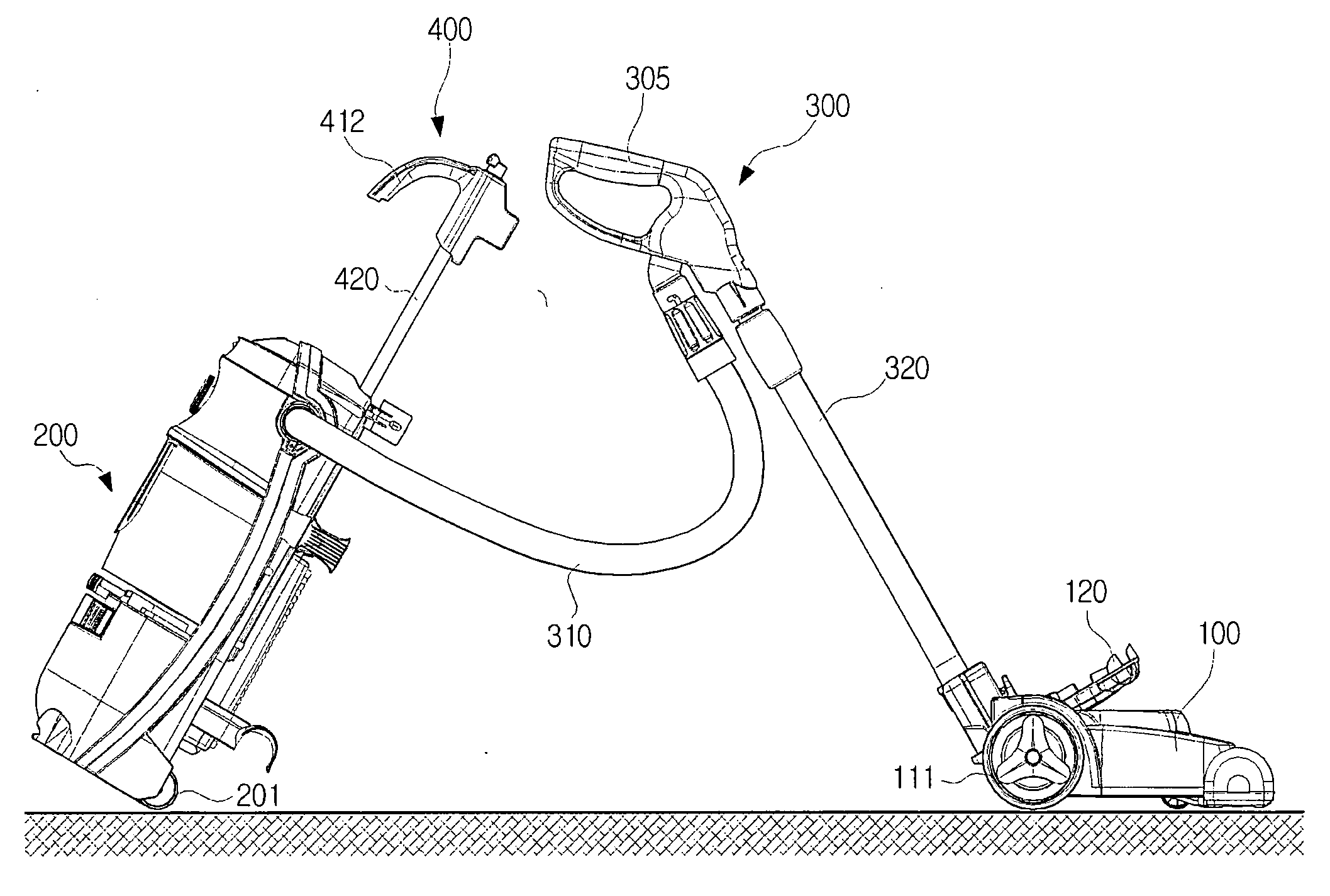
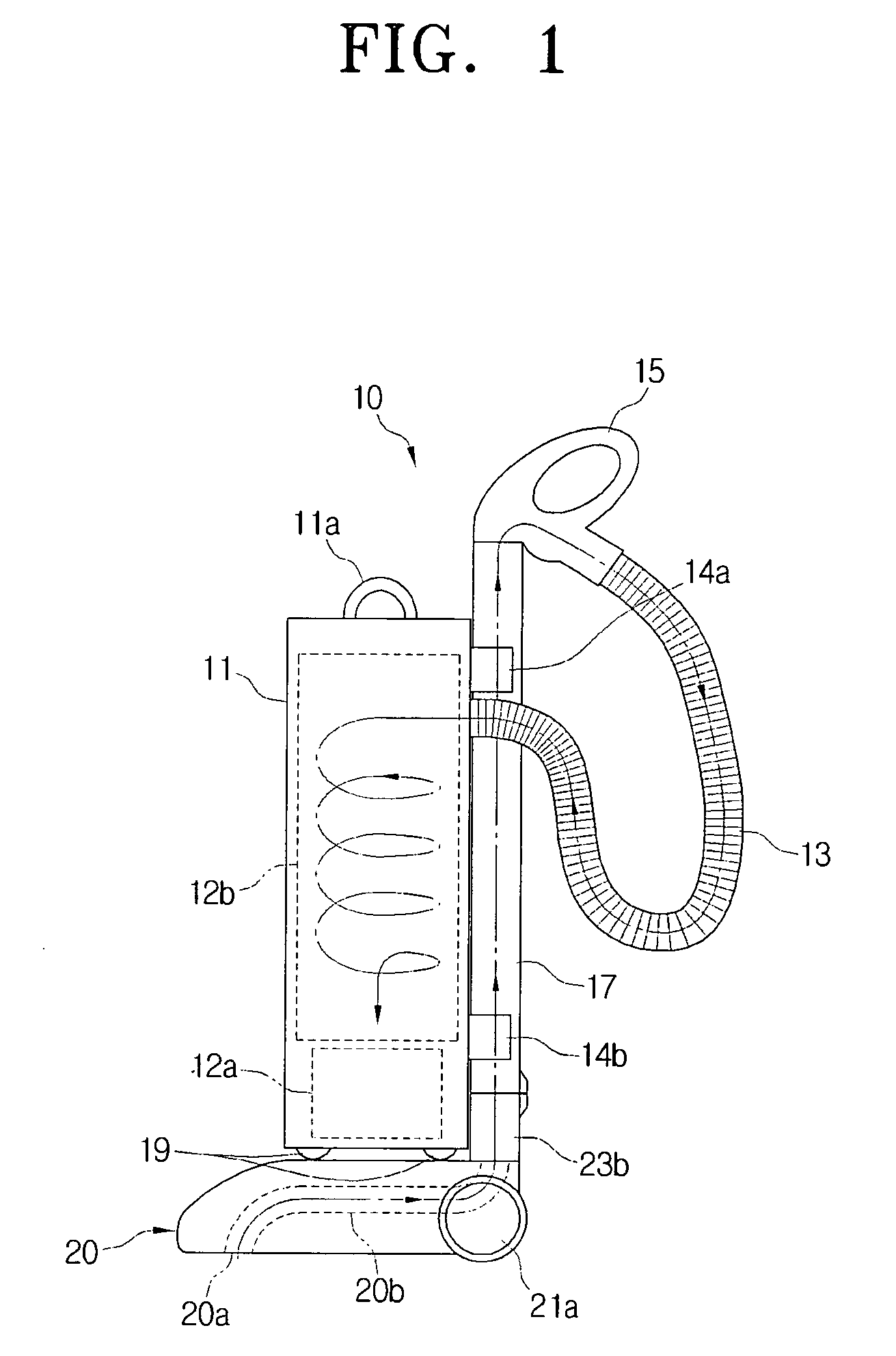
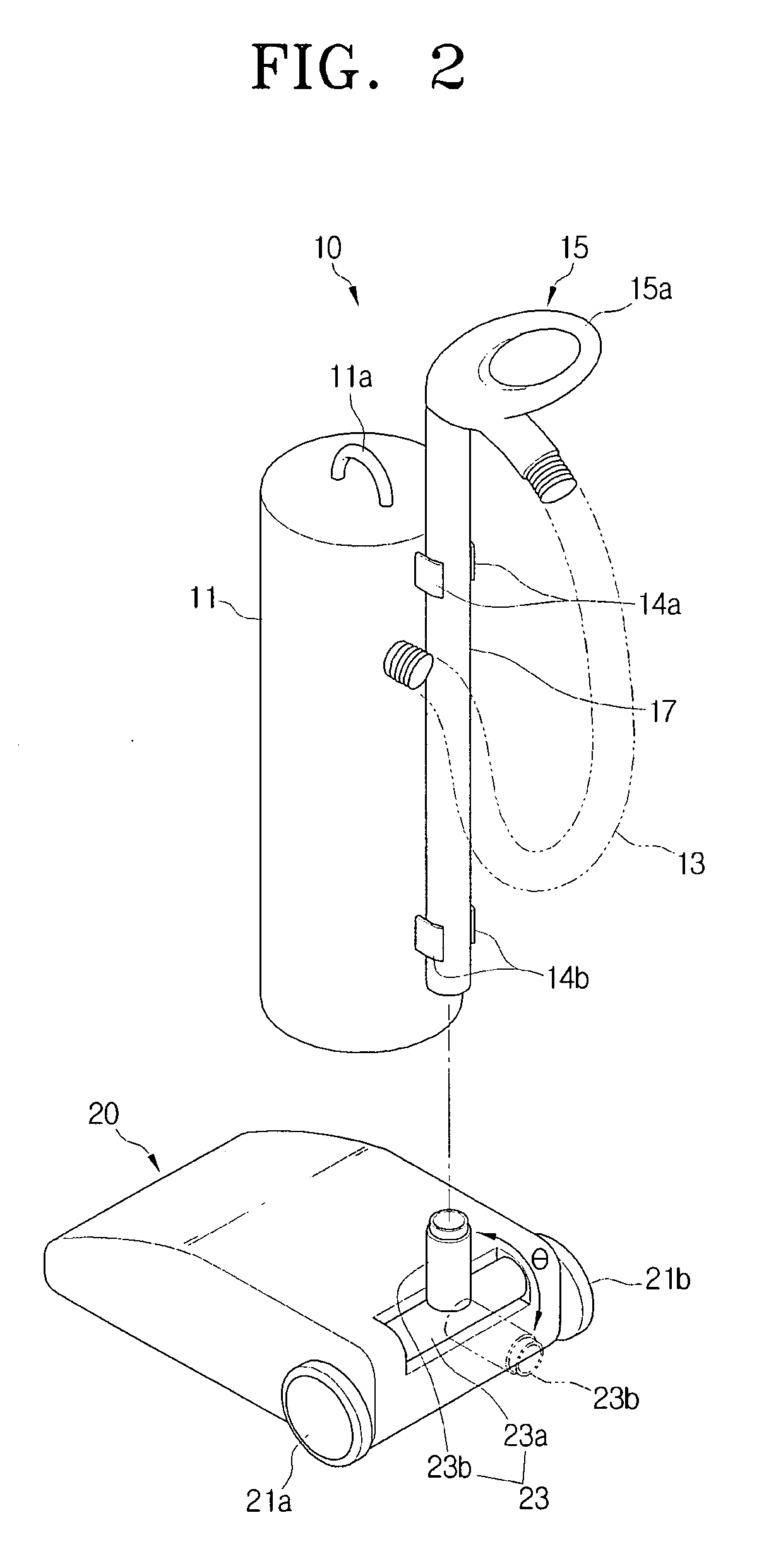
[0038]Referring to FIGS. 1 and 2, a vacuum cleaner according to a first exemplary embodiment of the present disclosure includes a cleaning unit 10 and a suction port assembly 20. The cleaning unit 10 may be separated from the suction port assembly 20 and used separately.

[0039]The cleaning unit 10 may include a cleaner body 11, a hose 13, an operating handle assembly 15, and an extension pipe 17.

[0040]The cleaner body 11 may include a suction motor 12a to generate a suction force inside th...


PUM


Abstract

A vacuum cleaner operable on upright mode and canister mode is provided. The vacuum cleaner includes a suction port assembly comprising a suction port and a suction passage to draw in dust-laden air, a cleaner body housing a dust separating unit and a motor connected with the dust separating unit, an operating handle assembly in fluid communication with the cleaner body through a hose and in fluid communication with an extension pipe, and a carrying handle assembly sliding along the cleaner body to increase in length. If the vacuum cleaner is in the upright mode, the extension pipe is in fluid communication with the suction port assembly, is used as a passage for air to pass toward the cleaner body, and supports the cleaner body, while if the vacuum cleaner is in the canister mode, the extension pipe is separated from the cleaner body.

Description

CROSS-REFERENCE TO RELATED APPLICATION[0001]This application claims priority from U.S. Provisional Application No. 60 / 964,676, filed on Aug. 14, 2007 in the United States Patent and Trademark Office (USPTO), Korean Patent Application No. 2007-0093884, filed on Sep. 14, 2007 in the Korean Intellectual Property Office, and Korean Patent Application No. 2007-0077662, filed on Aug. 2, 2007 in the Korean Intellectual Property Office, the entire disclosure of each of which is hereby incorporated by reference.BACKGROUND OF THE INVENTION[0002]1. Field of the Invention[0003]The present disclosure relates to a vacuum cleaner, and more particularly, to a vacuum cleaner capable of drawing in dust-laden air from a surface being cleaned using a suction force generated by a motor driven inside the cleaner body, filtering the dust from the drawn air, and discharging clean air to the outside of the cleaner body.[0004]2. Description of the Related Art[0005]Vacuum cleaners can be broadly classified in...

Claims


Application Information

Patent Timeline
Patent Type & Authority Applications(United States)
IPC IPC(8): A47L9/00A47L5/22A47L5/28A47L9/32A47L5/30A47L5/36
CPCA47L5/28A47L5/32A47L9/327A47L9/325A47L5/36
Inventor YOO, DONG-HUNPARK, YUN-HEECHOUNG, MYOUNG-SUNJUNG, IL-DU
Owner SAMSUNG GWANGJU ELECTRONICS CO LTD
Why Eureka
Try Eureka