
Convective system for a dryer installation

a dryer and convective technology, applied in the direction of drying solid materials, drying machines, drying machines with progressive movements, etc., can solve the problems of large surface area, large investment and operating costs, and considerable thermal energy loss, so as to reduce investment and operation costs, reduce mechanical energy consumption, and reduce thermal energy loss

Inactive Publication Date: 2009-02-05
SOLARONICS
View PDF55 Cites 6 Cited by
  • Summary
  • Abstract
  • Description
  • Claims
  • Application Information

AI Technical Summary

Benefits of technology

[0013]The objective of the present invention is to mitigate the restrictions of the known installations and to propose a convective system for a dryer installation having a more reduced consumption of mechanical energy and a more reduced loss of thermal energy and lower investment and operation costs.

Problems solved by technology

Such a mixing entails an important consumption of energy.
Such an installation, although functioning satisfactorily, thus implies a considerable consumption of mechanical energy and also a considerable loss of thermal energy, thus resulting in considerable investment and operating costs, and also occupies a large surface.
Although above described system has already improved the efficiency of the dryer installation to a large extent, there is still a major restriction to the system in that the mixing devices cannot withstand temperatures that are higher than e.g. 350° C., thereby limiting the temperature of the warm blown combustion products.

Method used


Image

  • Convective system for a dryer installation
  • Convective system for a dryer installation
  • Convective system for a dryer installation

Examples


Embodiment Construction

[0080]The present invention will be described with respect to particular embodiments and with reference to certain drawings but the invention is not limited thereto but only by the claims. The drawings described are only schematic and are non-limiting. In the drawings, the size of some of the elements may be exaggerated and not drawn on scale for illustrative purposes. The dimensions and the relative dimensions do not correspond to actual reductions to practice of the invention.

[0081]Furthermore, the terms first, second, third and the like in the description and in the claims, are used for distinguishing between similar elements and not necessarily for describing a sequence, either temporally, spatially, in ranking or in any other manner. It is to be understood that the terms so used are interchangeable under appropriate circumstances and that the embodiments of the invention described herein are capable of operation in other sequences than described or illustrated herein.

[0082]FIG....


PUM

PropertyMeasurementUnit
temperatureaaaaaaaaaa

Abstract

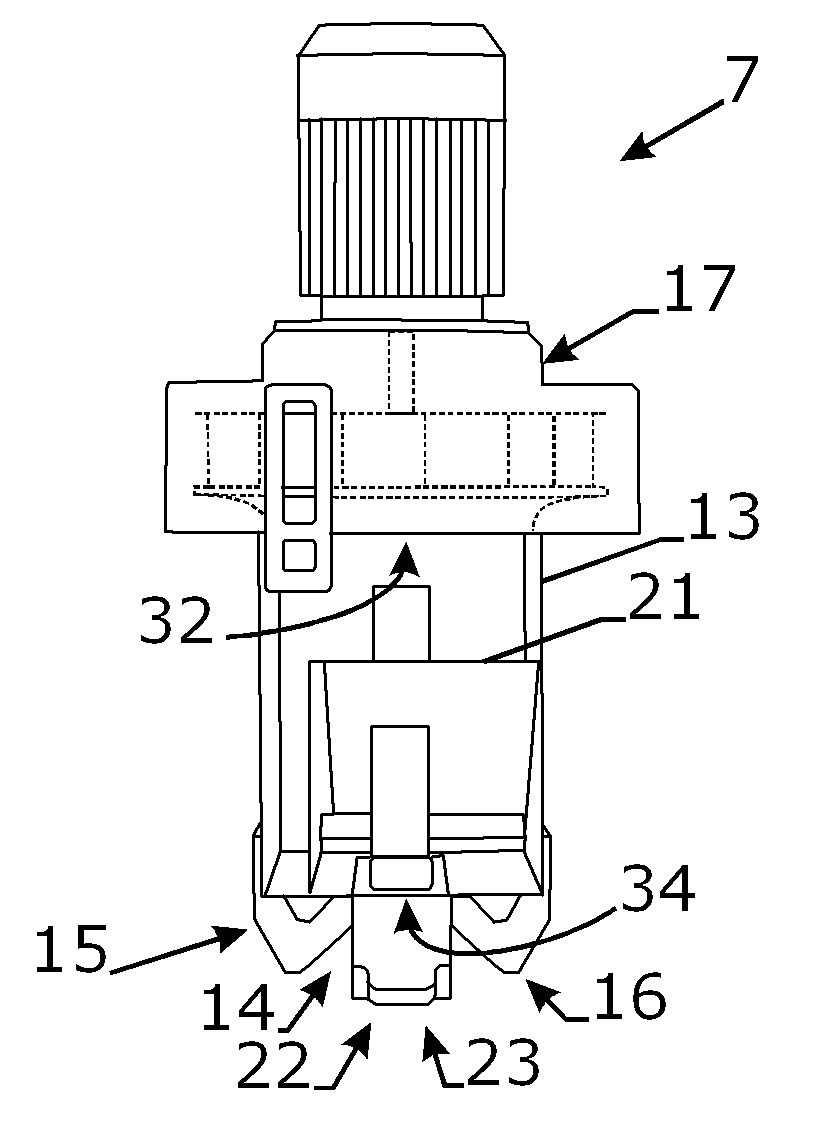
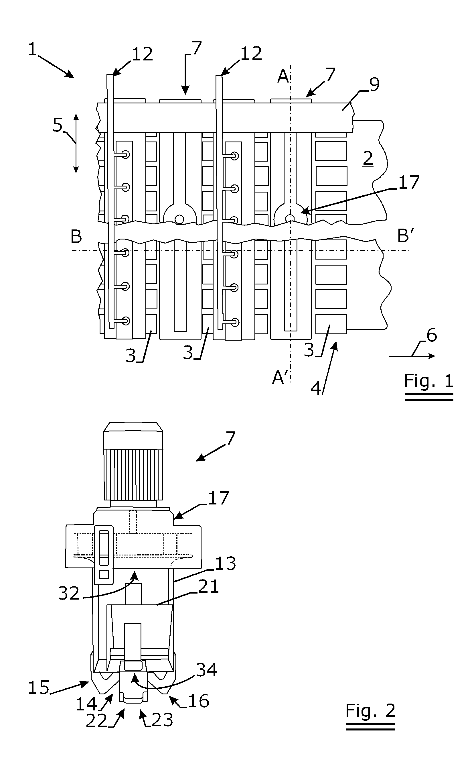
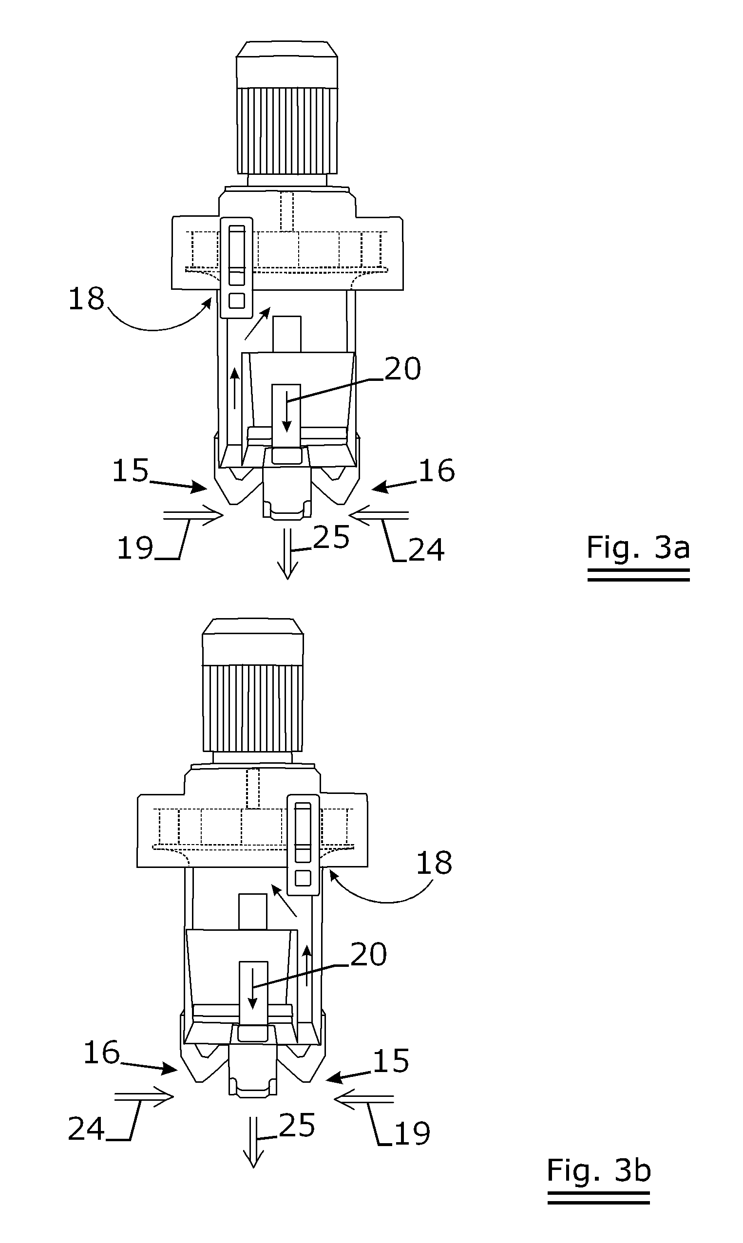
The present invention concerns a convective system for a dryer installation for a passing web, more particularly paper. The convective system 7 is an assembly of an exterior casing 13 for suction of combustion products with opening 14 towards the web, with a first 15 and second 16 suction ducts sucking the combustion products into the convective system 7. The combustion products coming from the first suction duct 15 are guided through the exterior casing 13 to a mixing and blowing device 17. Cold air 18 is mixed in this mixing and blowing device 17 with the combustion products 19, resulting in a gas mixture with lower temperature 20. The convective system 7 also has an internal casing 21 inside the external casing 13. This internal casing 21 has at least one opening towards the web 22 and has also openings 34 allowing gas flow from the mixing device 17 to the internal casing 21 of said gas mixture 20. Under the internal casing 21, there is also a blowing duct 23. The second suction duct 16 is also arranged under this internal casing 21 thereby extracting a second flow of combustion products 24 into the internal casing 21. This second flow 24 of combustion products is then mixed with the gas mixture 20 coming from the mixing device 17, resulting in a mixture of gasses 25 with a temperature that is higher than the first gas mixture 20 and higher than e.g. 350° C. or 370° C., more preferably 390° C. or 410° C., even more preferably 420° C., 450° C. or 500° C. These hot gasses 25 are then blown to the drying web by the blowing duct 23 of the internal casing 21.

Description

TECHNICAL FIELD[0001]The present invention concerns a convective system for a dryer installation for a passing web, more particularly paper.BACKGROUND ART[0002]There exists e.g. according to FR-A-2771161 in the name of the applicant an installation having at least a web, gas-heated radiant elements arranged according to at least one row stretching out in the transversal direction of the web, substantially over its entire width, and, downstream at least one row of radiant elements, at least a transverse convective system equipped with suction and blowing devices to suck at least part of the combustion products produced by the radiant elements and to blow this part of the combustion products towards the web. The installation generally also has devices to extract the warm gasses resulting from the convective exchanges between the passing web and the combustion products.[0003]The suction and blowing devices have a mixing device, such as e.g. a ventilator, that is, for several known reas...

Claims


Application Information

Patent Timeline
Patent Type & Authority Applications(United States)
IPC IPC(8): F26B13/00
CPCD21F5/008F26B13/22F26B13/10F26B3/305
Inventor LENOIR, PATRICK
Owner SOLARONICS
Learn More