Bicycle control device

a control device and bicycle technology, applied in bicycle brakes, cycle equipment, transportation and packaging, etc., can solve the problems of affecting the operation of the gear shift operating part, affecting and unintentional gear change, so as to facilitate the operation of the gear shift operation and the operation of the fingertip

Active Publication Date: 2009-02-05
SHIMANO INC
View PDF32 Cites 90 Cited by
  • Summary
  • Abstract
  • Description
  • Claims
  • Application Information

AI Technical Summary

Benefits of technology

[0023]A bicycle control device in accordance with an eleventh aspect of the present invention is the device in accordance with any one of the first to tenth aspects, wherein the brake lever has a side wall having a cut-away portion; and at least a portion of the first gearshift operating part is arranged inside the cut-away portion. With this aspect of the invention, since at least a portion of the first gearshift operating part is arranged inside the cut-away portion formed in a side wall of the brake lever, the first gearshift operating part can be moved easily while keeping one's figure on the brake lever.
[0024]A bicycle control device in accordance with a twelfth aspect of the present invention is the device in accordance with any one of the first to eleventh aspects, wherein the first and second gearshift operating parts are pivotally with respect to the brake lever with the first and second gearshift operating parts being pivoted in same directions with respect to the brake lever when a gear shift operation is performed by each of the first and second gearshift operating parts. With this aspect of the present invention, the first and second gearshift operating parts are easier to operate with a finger tip because both the first and second gearshift operating parts are contrived to pivot and the pivot direction of both ...

Problems solved by technology

For example, if one gearshift operating part is arranged near the finger tips and the other gearshift operating part is arranged closer to the palm of the hand, then the gearshift operating part arranged closer to the palm of the hand impedes the operation of the gearshift operating part arranged near the finger tips because the operating finger must reach across the gear shift member arranged closer to the palm ...

Method used


Image

  • Bicycle control device
  • Bicycle control device
  • Bicycle control device

Examples


Embodiment Construction

[0045]Selected embodiments of the present invention will now be explained with reference to the drawings. It will be apparent to those skilled in the art from this disclosure that the following descriptions of the embodiments of the present invention are provided for illustration only and not for the purpose of limiting the invention as defined by the appended claims and their equivalents.

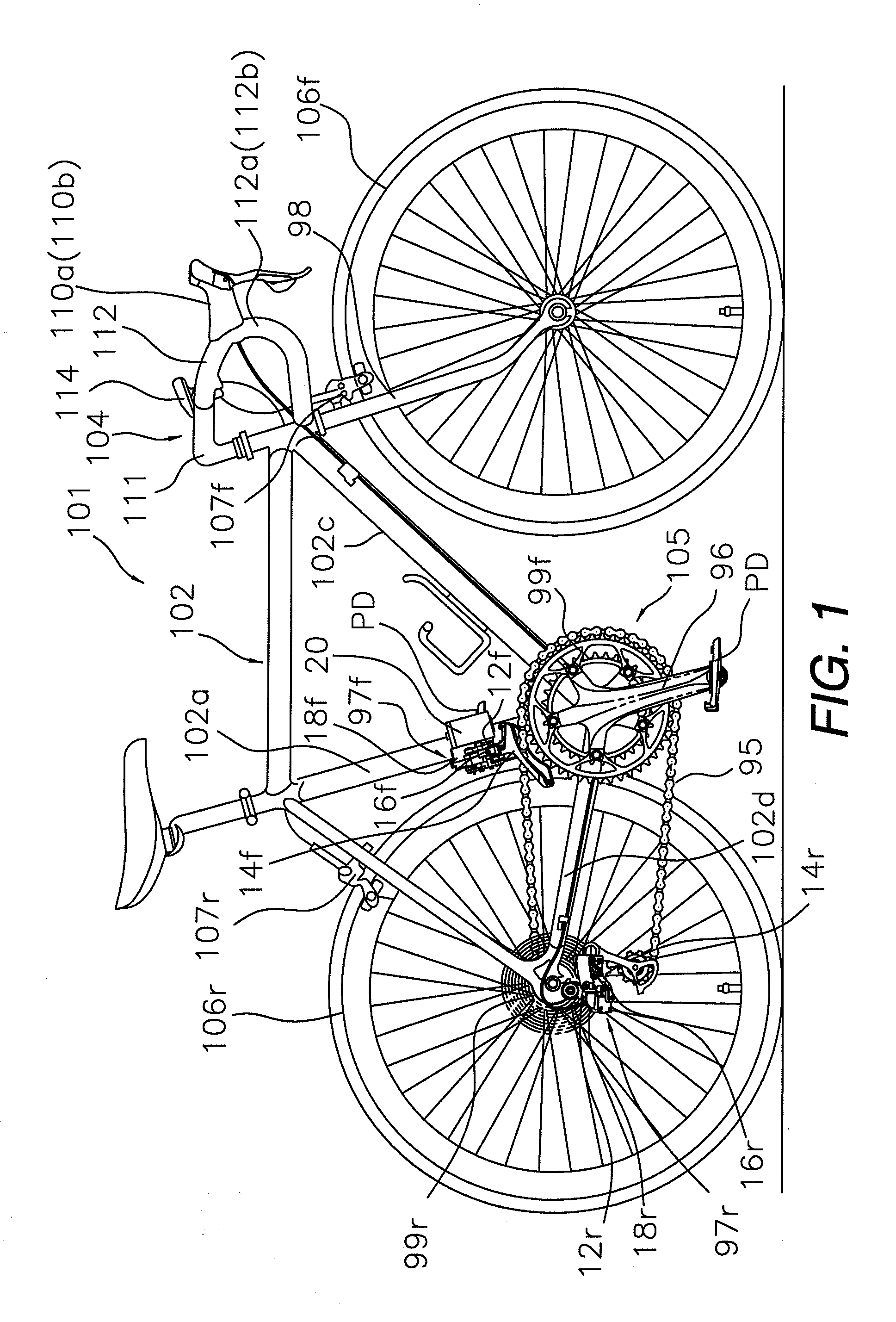
[0046]Referring initially to FIG. 1, a bicycle 101 is illustrated in accordance with a first embodiment of the present invention. FIG. 1 shows a bicycle 101 in which an embodiment of the present invention is employed. The bicycle 101 is a “road racer” (racing style road bike). The bicycle 101 basically includes a diamond-shaped frame 102 having a front fork 98, a handlebar unit 104 fastened to the front fork 98, a drive unit 105, a front wheel 106f mounted to the front fork 98 and a rear wheel 106r mounted to a rear portion of the frame 102. The drive unit 105 basically includes a chain 95, a crank...


PUM


Abstract

A bicycle control device is provided with a brake bracket, a brake lever, a first gearshift operating part, a second gearshift operating part, a first electrical switch, and a second electrical switch. The brake bracket is mountable to a handlebar. The brake lever is pivotally mounted to the brake bracket. The first gearshift operating part is movable relative to the brake lever. The second gearshift operating part is separate from the first gearshift operating part and movable relative to the brake lever. The first electrical switch is operated with the first gearshift operating part. The second electrical switch is operated with the second gearshift operating part. The second gearshift operating part is arranged such that when the first gearshift operating part is moved relative to the brake lever, the second gearshift operating part moves relative to the brake lever along with the first gearshift operating part.

Description

CROSS-REFERENCE TO RELATED APPLICATIONS[0001]This application claims priority under 35 U.S.C. §119 to Japanese Patent Application No. 2007-197683, filed Jul. 30, 2007. The entire disclosure of Japanese Patent Application No. 2007-197683 is hereby incorporated herein by reference.BACKGROUND OF THE INVENTION[0002]1. Field of the Invention[0003]This invention generally relates to a brake and gear shift device. More specifically, the present invention relates to a bicycle control device that is mounted to a handlebar of a bicycle for operating a braking device and for electrically operating an external gear changer apparatus.[0004]2. Background Information[0005]Bicycling is becoming an increasingly more popular form of recreation as well as a means of transportation. Moreover, bicycling has become a very popular competitive sport for both amateurs and professionals. Whether the bicycle is used for recreation, transportation or competition, the bicycle industry is constantly improving th...

Claims


Application Information

Patent Timeline
IPC IPC(8): B62M25/08
CPCB62K23/06B62L3/02Y10T74/20438Y10T74/2003Y10T74/20037B62M25/04
Inventor TETSUKA, TOSHIO
Owner SHIMANO INC
Why Eureka
Try Eureka