Seminconductor device having P-N column portion
a technology of semiconductor layer and peripheral portion, which is applied in the direction of semiconductor device details, semiconductor/solid-state device details, electrical apparatus, etc., can solve the problems of difficulties in the construction of low-concentration semiconductor layer as a peripheral portion, and achieve the effect of improving the breakdown voltage of the devi
- Summary
- Abstract
- Description
- Claims
- Application Information
AI Technical Summary
Benefits of technology
Problems solved by technology
Method used
Image

Examples
first embodiment
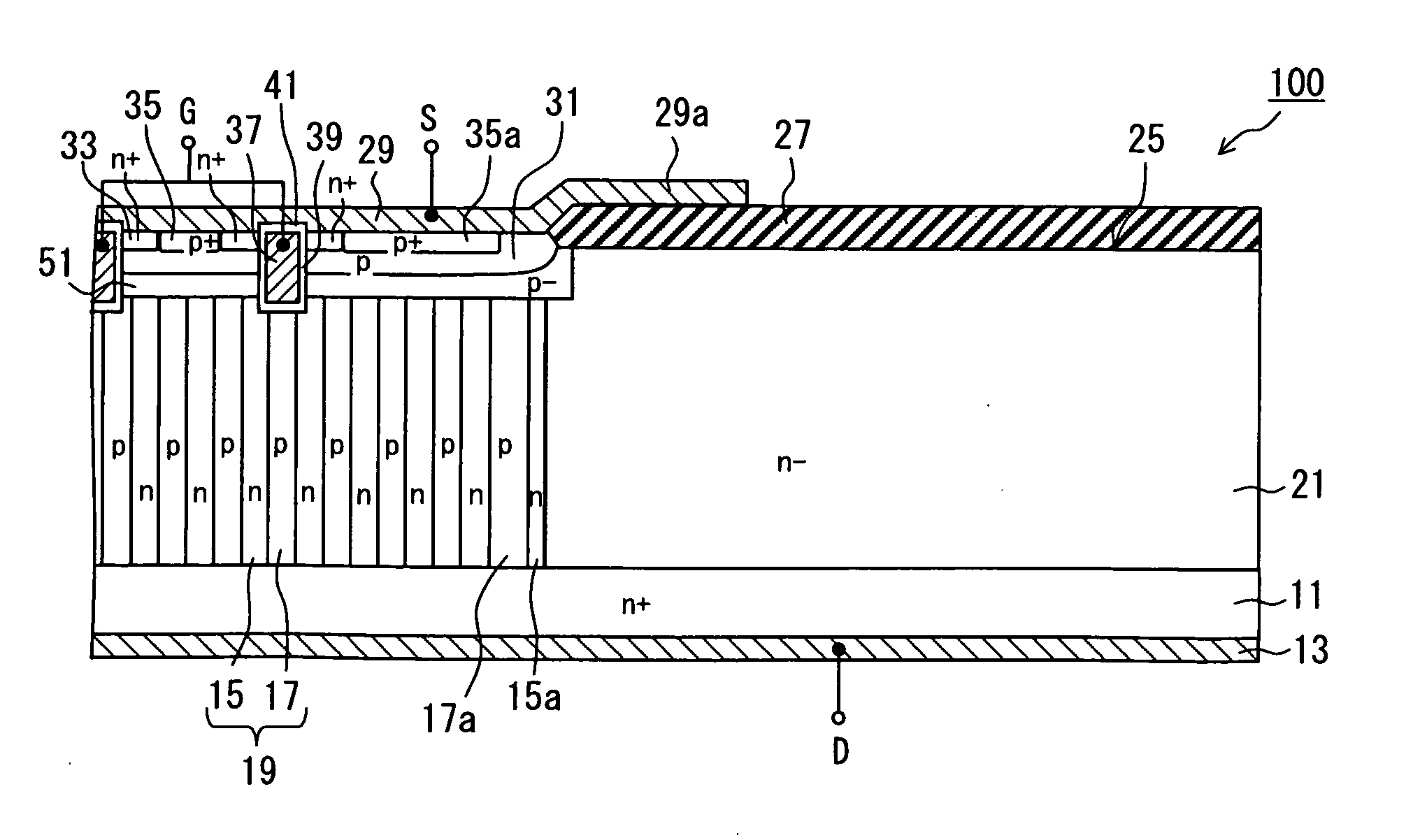
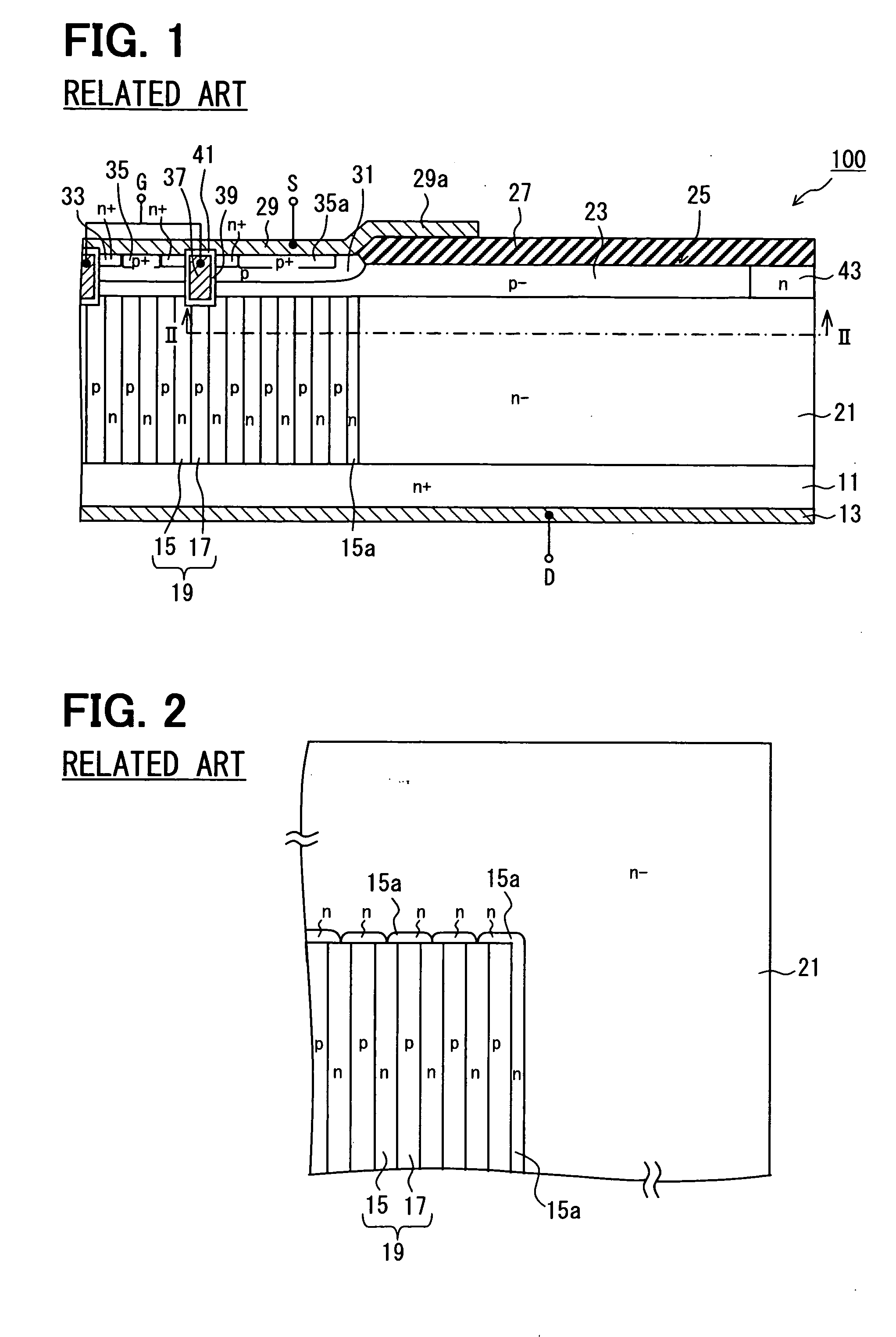
[0048]FIG. 5 is a sectional view illustrating the general configuration of a semiconductor device in a first embodiment. FIG. 6 is a sectional view taken along line VI-VI of FIG. 5. The same components as illustrated in FIG. 1 and FIG. 2 will be marked with the same reference numerals.
[0049]The semiconductor device in this embodiment is also formed by a publicly known trench burying method. Its basic configuration is the same as that of the semiconductor device 100 illustrated in FIG. 1 and FIG. 2. Hereafter, description will be given with a focus on a difference. The manufacturing method is described in, for example, JP-A-2006-173202 corresponding to US Patent Application Publication No. 2007-0238271, and its description will be omitted in the description of this embodiment.
[0050]As illustrated in FIG. 5 and FIG. 6, the following measure is taken in the semiconductor device 100 in this embodiment. The drain electrode 13 is disposed over the surface of the n+-type substrate 11 as a ...
second embodiment
[0070]FIG. 11 is a sectional view illustrating the general configuration of a semiconductor device in a second embodiment. FIG. 12 is a sectional view taken along line XII-XII of FIG. 11. The same elements as components illustrated in FIG. 1 and FIG. 2 or described in relation to the first embodiment will be marked with the same reference numerals.
[0071]The semiconductor device in this embodiment is identical with the semiconductor device 100 in the first embodiment in basic configuration, and is different in that it has multiple p-type semiconductor layers 17 larger in impurity amount.
[0072]As illustrated in FIG. 11 and FIG. 12, the semiconductor device 100 in this embodiment has the following as a semiconductor layer larger in impurity amount than the other p-type semiconductor layers 17: in addition to the outermost p-type semiconductor layer 17a in the first embodiment, it has the p-type semiconductor layer 17b adjacent to the p-type semiconductor layer 17a. That is, of the p-ty...
third embodiment
[0079]FIG. 14 is a sectional view illustrating the general configuration of a semiconductor device in a third embodiment. FIG. 15 is a sectional view taken along line XV-XV of FIG. 14. The same elements as components illustrated in FIG. 1 and FIG. 2 or described in relation to the first embodiment or the second embodiment will be marked with the same reference numerals.
[0080]The semiconductor device in this embodiment is identical with the semiconductor device 100 in the first embodiment in basic configuration and is different in the following point: a p-type semiconductor layer 17 is taken as the end semiconductor layer of the p-n column portion 19; and some of the n-type semiconductor layers 15 counted from the end semiconductor layer side are smaller in impurity amount than the other n-type semiconductor layers 15. The semiconductor device 100 of this construction can be formed, for example, by the following procedure: trenches are formed in an n−-type semiconductor layer; therea...
PUM
 Abstract
Description
Claims
Application Information
 - R&D
- Intellectual Property
- Life Sciences
- Materials
- Tech Scout
- Unparalleled Data Quality
- Higher Quality Content
- 60% Fewer Hallucinations
Browse by: Latest US Patents, China's latest patents, Technical Efficacy Thesaurus, Application Domain, Technology Topic, Popular Technical Reports.
© 2025 PatSnap. All rights reserved.Legal|Privacy policy|Modern Slavery Act Transparency Statement|Sitemap|About US| Contact US: help@patsnap.com