
Vehicle Door Latch Assembly

a technology for vehicle doors and latches, applied in the field of vehicle door latches, can solve the problems of no longer being able to engage the lock rod or the inside locking lever, and achieve the effects of reducing costs, protecting from potential freezing issues, and saving cost and assembly tim

Active Publication Date: 2009-02-05
GM GLOBAL TECH OPERATIONS LLC
View PDF16 Cites 34 Cited by
  • Summary
  • Abstract
  • Description
  • Claims
  • Application Information

AI Technical Summary

Benefits of technology

[0007]An advantage of an embodiment is that the inside locking lever is located in the door dry cavity, and so is protected from potential freezing issues.
[0008]An advantage of an embodiment is that the lock rod, being located entirely inboard of the door inner panel, is protected from theft attempts. A thief sliding a tool between the inside of the window glass and the door inner panel will no longer be able to engage the lock rod or inside locking lever in an attempt to unlock the door. This also eliminates the need for any type of anti-theft shielding to be mounted near the lock rod, which may save cost and assembly time.
[0009]An advantage of an embodiment is that a lock rod grommet mounted in the door inner panel is no longer needed. This may reduce costs and eliminates a potential leak path for water between the door wet cavity and the door dry cavity. Elimination of the grommet may also reduce the inside manual lock button operating effort and improve the feel when manually unlocking the door latch, as well as reduce the load on a power lock motor.
[0010]An advantage of an embodiment is that assembly of the lock rod to the inside locking lever may be easier. The inside locking lever and lock rod are now located on the inboard side of the door inner panel (rather than located between the door inner and outer panels as is conventional) making assembly of the lock rod to inside locking lever easier during vehicle assembly since blind assembly is no longer required. Moreover, an electrical connector may also be received through the same access hole in the door inner panel, thus reducing the cost and complexity of routing and sealing a wiring harness extending through the door inner panel that connects to the electrical connector.

Problems solved by technology

A thief sliding a tool between the inside of the window glass and the door inner panel will no longer be able to engage the lock rod or inside locking lever in an attempt to unlock the door.

Method used


Image

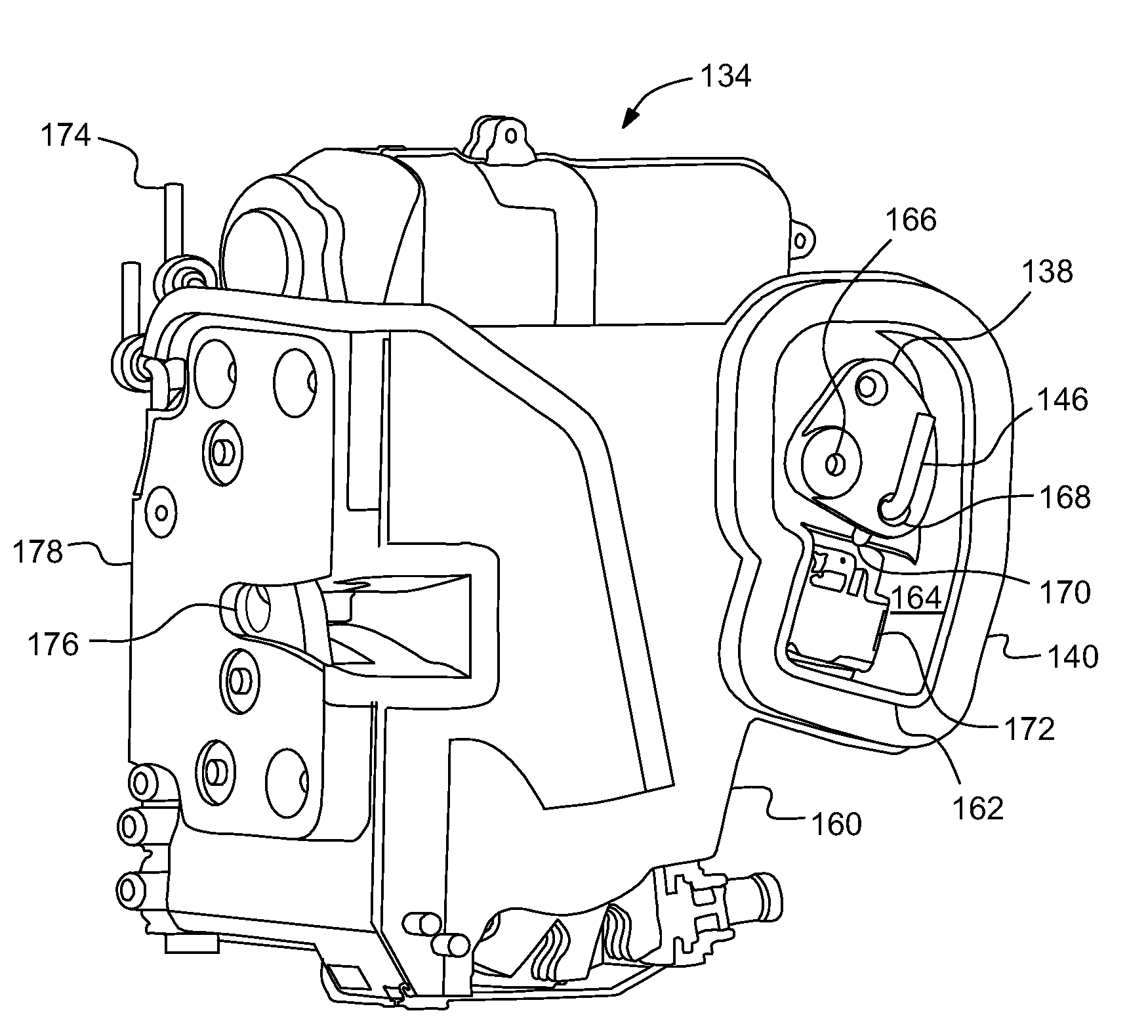
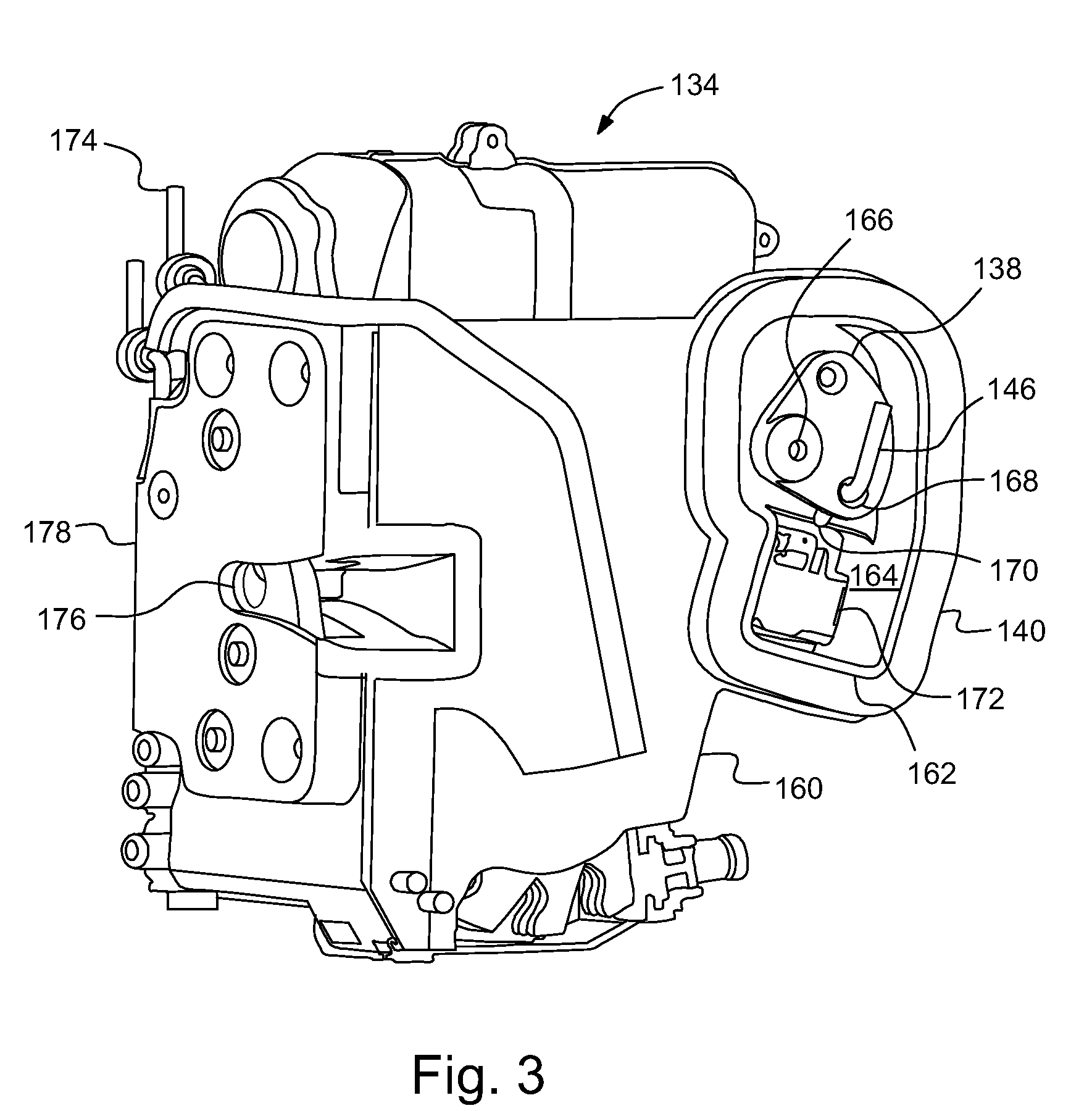
  • Vehicle Door Latch Assembly
  • Vehicle Door Latch Assembly
  • Vehicle Door Latch Assembly

Examples


Embodiment Construction

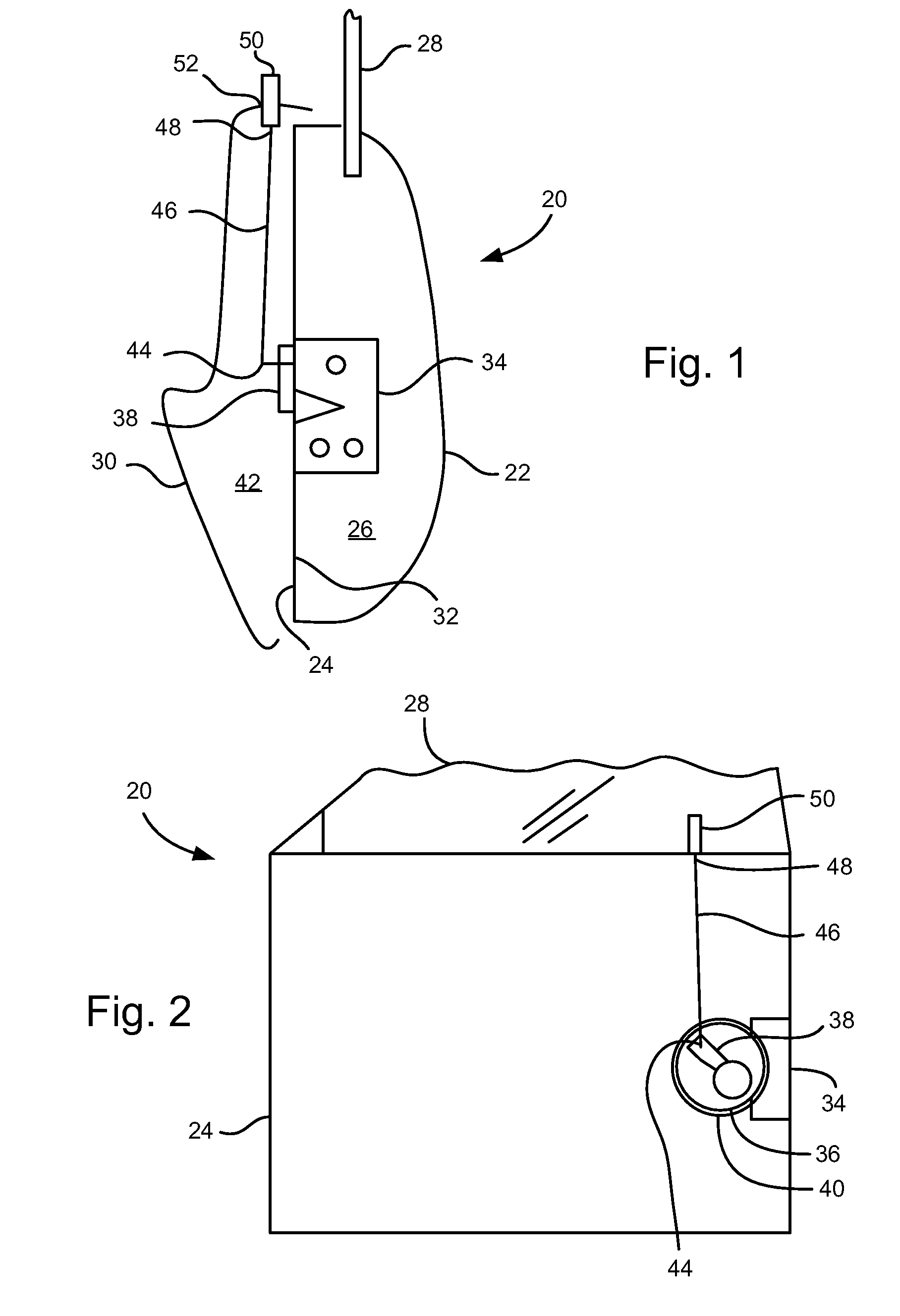
[0016]Referring to FIGS. 1-2, a vehicle door, indicated generally at 20, is shown. The vehicle door 20 may be a side door or other hinged door on a vehicle that includes a movable window and a lock mechanism. The vehicle door 20 includes a door outer panel 22, forming an outboard surface of the door 20, and a door inner panel 24, which is inboard of the door outer panel 22. The door outer and inner panels 22, 24 are secured together to form a door wet cavity 26. A movable window glass 28 mounts between the door outer and inner panels 22, 24 and can slide up and down in the door wet cavity 26. With the window 28 being able to slide up and down, water can relatively easily get into the wet cavity 26.

[0017]A door trim panel 30 mounts on the inboard side of the door inner panel 24. The door inner panel 24 is sealed, forming a door seal surface 32 that prevents water in the door wet cavity 26 from passing through the door inner panel 24. Thus, a door dry cavity 42 is defined between the ...


PUM


Abstract

A vehicle door and a vehicle door latch assembly is disclosed. The vehicle door includes a door outer panel; a door inner panel affixed to the door outer panel and defining a door wet cavity, with the door inner panel including an access hole; and a door trim panel mounted to the door inner panel and defining a door dry cavity. A door latch is located in the door wet cavity; a latch locking lever is exposed to the door dry cavity and shielded from the door wet cavity, with the latch locking lever engaging the door latch; and a lock rod has a first end attached to the latch locking lever, with the lock rod extending through the access hole and between the door inner panel and the door trim panel, whereby the lock rod is not exposed to the door wet cavity.

Description

CROSS REFERENCE TO RELATED APPLICATIONS[0001]This application claims the benefit of U.S. Provisional Application No. 60 / 953,522, filed Aug. 2, 2007, which is incorporated herein by reference.BACKGROUND OF INVENTION[0002]The present invention relates generally to vehicle door lock assemblies.[0003]Conventional vehicle doors, particularly those with movable window glass, often have an inside manual lock button. The inside manual lock button extends upward through a hole in the door trim panel, allowing one to manually unlock the door from inside the vehicle by grasping and pulling up on this button, or lock the door by pushing down on the button. The lock button connects to a lock mechanism on the door latch via a lock rod and an inside locking lever. The lock rod is attached to the lock button, and extends downward between the door trim panel and a door inner panel—in a dry area of the door. The lock rod then bends and extends outboard through a grommet mounted in the door inner pane...

Claims


Application Information

Patent Timeline
IPC IPC(8): E05C3/06
CPCB60J5/0416E05B85/08E05B85/02E05B77/34Y10T292/1047
Inventor KONCHAN, JEFFREY L.ARABIA, JR., FRANK J.
Owner GM GLOBAL TECH OPERATIONS LLC
Learn More