Scalable distributed redundancy

a distributed redundancy and power distribution technology, applied in the direction of dc network circuit arrangements, emergency power supply arrangements, transportation and packaging, etc., can solve the problems of loss of redundancy, critical load interruption, and inacceptable risk of critical load interruption

Active Publication Date: 2009-02-05
NTT GLOBAL DATA CENTS AMERICAS INC
View PDF58 Cites 28 Cited by
  • Summary
  • Abstract
  • Description
  • Claims
  • Application Information

AI Technical Summary

Benefits of technology

[0013]The systems and methods of the invention allow the power distribution system to grow step by step without interruptions to the load or reductions in the redundancy of the power distribution system. To allow the power distribution system to grow step by step without the

Problems solved by technology

When the connection is changed, the B connection is removed and the circuit is rerun or rerouted and connected to C. A problem with changing the connection is a loss of redundancy during the transition.
However, if the A source fails while the B source is being changed to C, this reduction in redundancy results in a cr

Method used


Image

  • Scalable distributed redundancy
  • Scalable distributed redundancy
  • Scalable distributed redundancy

Examples


Embodiment Construction

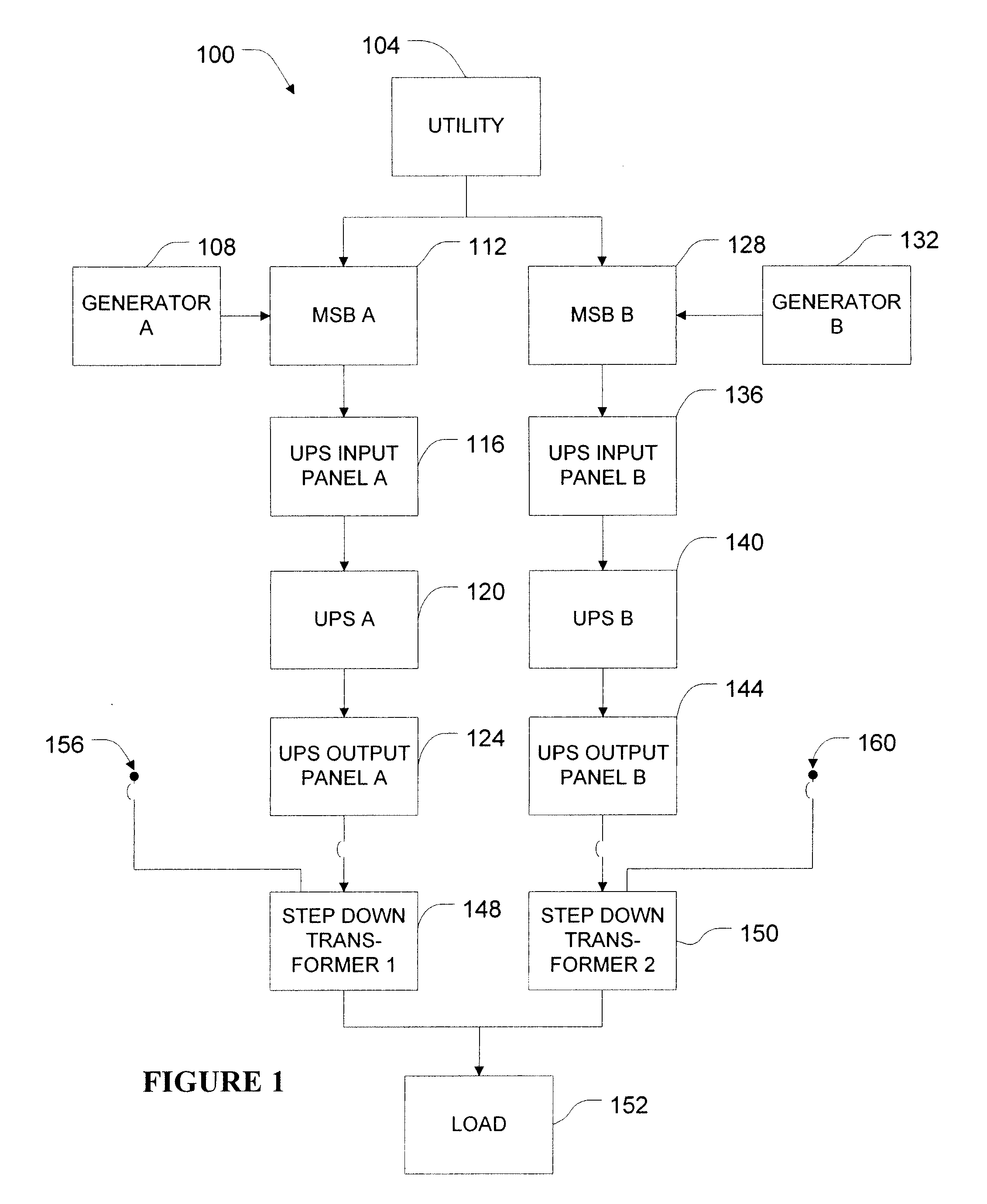
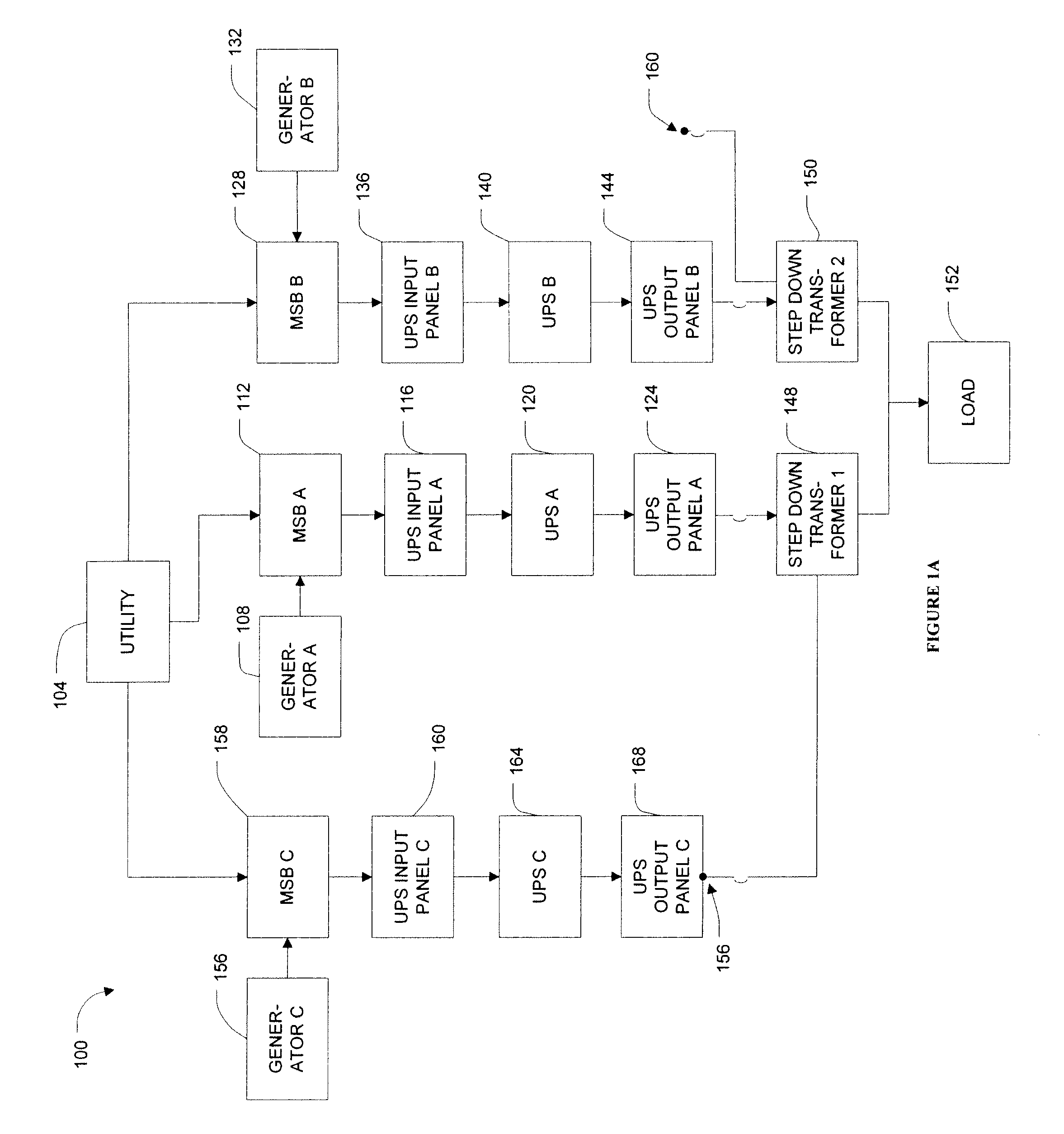
[0051]An embodiment of the invention will now be described in detail with reference to FIG. 1. FIG. 1 illustrates an exemplary power distribution system 100. The power distribution system 100 includes a connection to a utility 104 and a generator A 108 that are both connected to a main switch board (MSB) A 112. The MSB A 112 is connected to an uninterruptible power supply (UPS) input panel A 116 that is connected to a UPS A 120, which is connected to a UPS Output panel A 124. Similarly, the utility 104 and generator B 132 are connected to the MSB B 128. The MSB B 128 is connected to a UPS input panel B 136, UPS B 140 and UPS Output Panel B 144. The UPS Output Panel A 124 is connected to a first step down transformer (hereinafter referred to as “transformer”) 148, and the Output Panel B 144 is connected to a second transformer 150. The transformers 148, 150 are connected to a load block 152. The first transformer 148 also includes an open connection 156 and the second transformer 150...


PUM


Abstract

A scalable power distribution system for a data center and methods for scaling a power distribution system are described. The scalable power distribution system includes a transformer that is connected to a load at its output. The input of the transformer is connected to two isolation switches. A source is connected to one switch at all times, and the source can be switched without affecting power to the load by synchronizing the two sources at the transformer before switching sources. The load is not de-energized at any time during the transfer process.

Description

CROSS-REFERENCE TO RELATED APPLICATIONS[0001]This application claims the benefit of U.S. Provisional Application No. 60 / 953,878, filed Aug. 3, 2007, entitled “SCALABLE DISTRIBUTED REDUNDANCY,” the entirety of which is hereby incorporated by reference.BACKGROUND[0002]1. Field[0003]The subject invention relates to power distribution systems and in particular to a scalable power distribution system.[0004]2. Related Art[0005]Power distribution systems are typically used in facilities to convert transmitted high voltage energy to energy that is suitable for its intended use and deliver that energy within the facility. These facilities (e.g., hospitals, data centers, etc.) have a load (e.g., computers, heating and air conditioning equipment, etc.) to which the energy is delivered by the power distribution system. An exemplary power distribution system that is used in these facilities is a distributed redundant power system.[0006]In a distributed redundant power distribution system, N+1 re...

Claims


Application Information

Patent Timeline
IPC IPC(8): H02J3/00H02J9/00
CPCH02J9/06
Inventor LINKHART, CHARLES O.MISHRA, YATISH C.MACRICOSTAS, GEORGE
Owner NTT GLOBAL DATA CENTS AMERICAS INC
Why Eureka
Try Eureka