Fusing device and image apparatus having the same

Active Publication Date: 2009-02-05
HEWLETT PACKARD DEV CO LP
View PDF3 Cites 13 Cited by
  • Summary
  • Abstract
  • Description
  • Claims
  • Application Information

AI Technical Summary

Benefits of technology

[0013]Aspects of the present invention has been made in order to solve the above and/or other problems. It is an aspect of the i

Problems solved by technology

However, in this case, a diameter of the heating roller has to be accordingly enlarged, thereby increasing the size of the fusing device.
This increases the size of

Method used


Image

  • Fusing device and image apparatus having the same
  • Fusing device and image apparatus having the same
  • Fusing device and image apparatus having the same

Examples


Example

[0042]Reference will now be made in detail to the exemplary embodiments of the present invention, examples of which are illustrated in the accompanying drawings, wherein like reference numerals refer to like elements throughout. The exemplary embodiments are described below, in order to explain the aspects of the present invention, by referring to the figures.

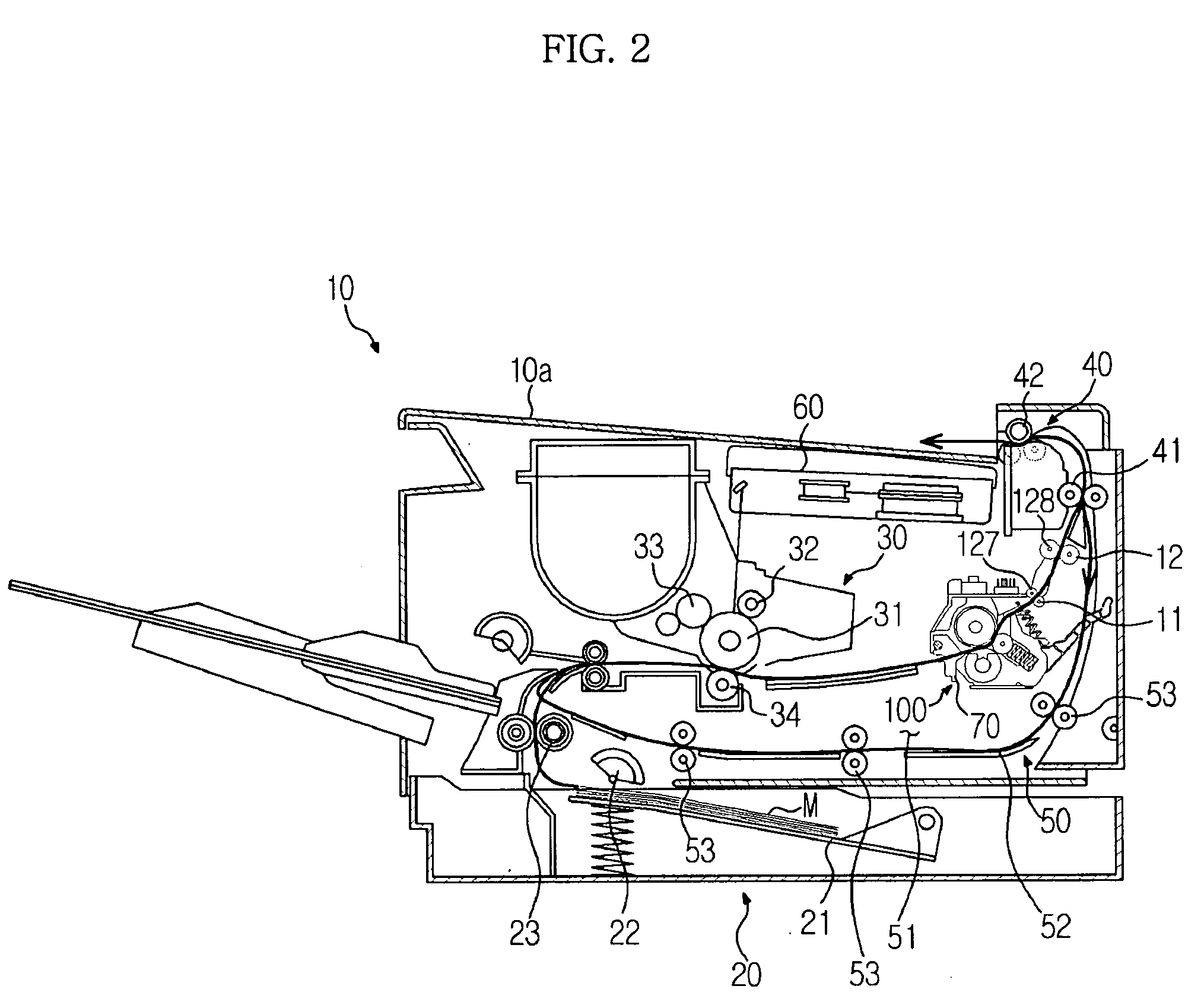
[0043]FIG. 2 is a view showing the structure of an image forming apparatus 10, according to an exemplary embodiment of the present invention. Referring to FIG. 2, the image forming apparatus 10 comprises a main body 10a, a printing medium feeding device 20, a developing device 30, a fusing device 100, a discharging device 40, and a duplex printing device 50.

[0044]The printing medium feeding device 20 feeds a printing medium M to the developing device 30. The printing medium feeding device 20 comprises a tray 21 to store the printing medium M, a pickup roller 22 to pickup the printing medium M from the tray 21, sheet by sheet, a...


PUM


Abstract

A fusing device comprising: a frame; a cover hinged to the frame, a heating roller mounted in the cover; a first pressing roller to form a first fusing nip through contact with the heating roller; a second pressing roller to form a second fusing nip, through which a printing medium passes, after passing through the first fusing nip; and a first resilient member connected to the frame and the cover, to bias the first and second pressing rollers toward the heating roller.

Description

CROSS-REFERENCE TO RELATED APPLICATIONS[0001]This application claims the benefit of Korean Patent Application Nos. 2007-77749 filed on Aug. 2, 2007 and 2007-141699 filed on Dec. 31, 2007, in the Korean Intellectual Property Office, the disclosure of which is incorporated herein by reference.BACKGROUND OF THE INVENTION[0002]1. Field of the Invention[0003]Aspects of the present invention relate to an image forming apparatus, and more particularly, to a fusing device having improved performance and compactness, and an image forming apparatus having the same.[0004]2. Description of the Related Art[0005]In general, an image forming apparatus refers to an apparatus that forms an image on a printing medium, in accordance with input image signals. For example, a printer, a photocopier, a facsimile, and a multifunction peripheral (MFP) having combined functions of the aforementioned apparatuses, are examples of image forming apparatuses.[0006]An electrophotographic image forming apparatus fo...

Claims


Application Information

Patent Timeline
IPC IPC(8): G03G15/20
CPCG03G15/206
Inventor CHANG, HYUK JAE
Owner HEWLETT PACKARD DEV CO LP
Why Eureka
Try Eureka